Help Identifying these codes

Dec 5, 2006
153
0
17
I had got some codes pulled and need some help with a code 94 and 44 with the engine running, i'm using the obd1 code reader but lost the manual, when i performed the test there's also a O on the right corner of the reader on 94 and 44.

With the key on engine off iv got a code 67 o ,10, 18c . The smog on the car is removed so i don't know if any of these codes have anything to do with it but any help is appreciated.
 
Codes 44 & 94 - AIR system inoperative - Air Injection. Check vacuum lines for leaks, & cracks.

Revised 28-Oct-2009 to correct code definitions and operation.

Code 44 RH side air not functioning.
Code 94 LH side air not functioning.

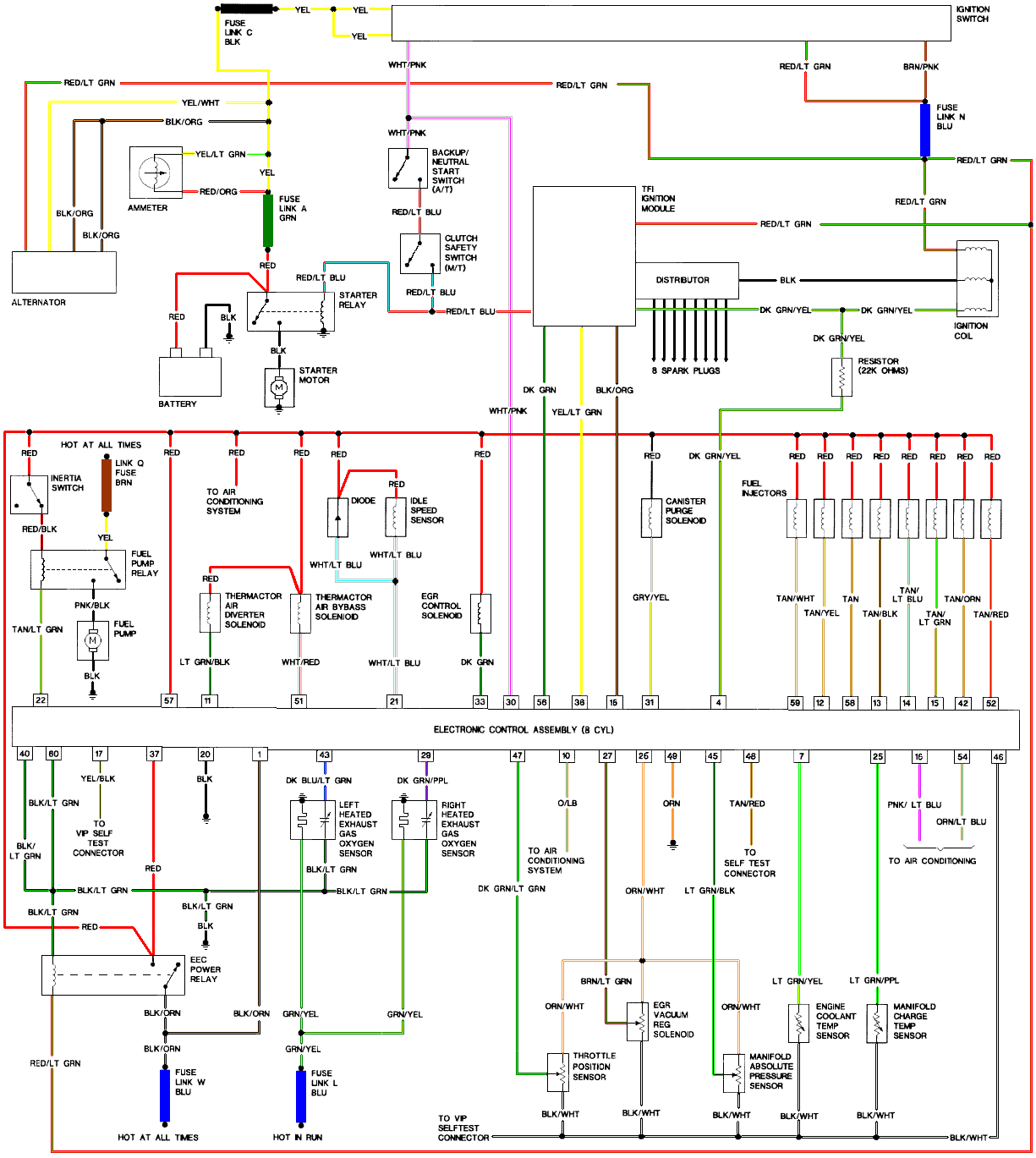
The computer uses the change in the O2 sensor readings to detect operation of the Thermactor control valves. When the dump valve opens, it reduces the O2 readings in the exhaust system. Then it closes the dump valve and the O2 readings increase. By toggling the dump valve (TAB), the computer tests for the 44/94 codes.

Failure mode is usually due to a clogged air crossover tube, where one or both sides of the tube clog with carbon. The air crossover tube mounts on the back of the cylinder heads and supplies air to each of the Thermactor air passages cast into the cylinder heads. When the heads do not get the proper air delivery, they set codes 44 & 94, depending on which passage is clogged. It is possible to get both 44 & 94, which would suggest that the air pump or control valves are not working correctly, or the crossover tube is full of carbon or missing.

Testing the system:
Disconnect the big hose from smog pump: with the engine running you should feel air output. Reconnect the smog pump hose & apply vacuum to the first vacuum controlled valve: Its purpose is to either dump the pump's output to the atmosphere or pass it to the next valve.

The next vacuum controlled valve directs the air to either the cylinder heads when the engine is cold or to the catalytic converter when the engine is warm. Disconnect the big hoses from the back side of the vacuum controlled valve and start the engine. Apply vacuum to the valve and see if the airflow changes from one hose to the next.

The two electrical controlled vacuum valves mounted on the rear of the passenger side wheel well turn the vacuum on & off under computer control. Check to see that both valves have +12 volts on the red wire. Then ground the white/red wire and the first solenoid should open and pass vacuum. Do the same thing to the light green/black wire on the second solenoid and it should open and pass vacuum.

Remember that the computer does not source power for any actuator or relay, but provides the ground necessary to complete the circuit. That means one side of the circuit will always be hot, and the other side will go to ground or below 1 volt as the computer switches on that circuit.

The computer provides the ground to complete the circuit to power the solenoid valve that turns the
vacuum on or off. The computer is located under the passenger side kick panel. Remove the kick panel & the cover over the computer wiring connector pins. Check Pin 38 Solenoid valve #1 that provides vacuum to the first Thermactor control valve for a switch from 12-14 volts to 1 volt or less. Do the same with pin 32 solenoid valve #2 that provides vacuum to the second Thermactor control valve. Starting the engine with the computer jumpered to self test mode will cause all the actuators to toggle on and off. If after doing this and you see no switching of the voltage on and off, you can start testing the wiring for shorts to ground and broken wiring. An Ohm check to ground with the computer connector disconnected & the solenoid valves disconnected should show open circuit between the pin 32 and ground and again on pin 38 and ground. In like manner, there should be less than 1 ohm between pin 32 and solenoid valve #2 and pin 38 & Solenoid valve #1.

If after checking the resistance of the wiring & you are sure that there are no wiring faults, start looking at the solenoid valves. If you disconnect them, you can jumper power & ground to them to verify operation. Power & ground supplied should turn on the vacuum flow, remove either one and the vacuum should stop flowing.

Typical resistance of the solenoid valves is in the range of 20-70 Ohms.

See the following website for some help from Tmoss (diagram designer) & Stang&2Birds (website host)

http://www.veryuseful.com/mustang/tech/engine/images/fuel-alt-links-ign-ac.gif

http://www.veryuseful.com/mustang/tech/engine/images/88-91eecPinout.gif

See http://forums.stangnet.com/attachment.php?attachmentid=50636&d=1180923382 for a very nice drawing of the Thermactor Air System (smog pump) plumbing

If you have a catalytic converter H pipe, you need to fix these codes. If you don't, then don't worry about them
 
Code 10 is a separator code that you can ignore.

Code 18 - SPOUT out or wiring fault - look missing SPOUT jumper, short to ground or open circuit in SPOUT wiring going back to the computer. Possible bad TFI.

The SPOUT enables the distributor to advance the timing beyond the base setting. Without a working SPOUT, you are locked down to the timing you set with the timing light.

Checking the SPOUT wiring
Tools needed:

DVM or Ohmmeter
10 MM wrench
Phillips screwdriver.
6 ft 16 or 18 gauge jumper wire with alligator clips on each end.

Anytime you make resistance checks, the circuit under test must not be powered on. If it is powered up during the test, your readings will be wrong and you may damage the meter. Do not touch the probe tips when making resistance measurements. If you do, your readings may be inaccurate.

Remove the SPOUT connector from the ignition harness by the distributor. Remove the passenger side kick panel and loosen the 10 MM bolt that secures the computer wiring connector. Use your DVM to measure the resistance between ground and pin 36 (yellow/lt green wire): you should see and infinite open circuit. Keep the DVM connected to pin 36 (you may need a helper at this point). Insert the DVM lead you previously had connected to the body ground into the computer side of the SPOUT connector. You may need some extra wire to extend the test lead, so have some 16-18 gauge insulated wire handy. If you extend the test lead, remember that the quality of the connections may affect your readings. You should see less than 2.0 Ohms: more than that indicates a wiring problem

The following is a view from the computer side of the computer wiring connector.
eec04.gif


Diagrams courtesy of Tmoss & Stang&2birds
Mustang-86-Mustang-ECC-EFI.gif


See the following website for some help from Tmoss (diagram designer) & Stang&2Birds
(website host) for help on 86-95 5.0 Mustang wiring Mustang FAQ - Engine Information Everyone should bookmark this site.


Ignition switch wiring
http://www.veryuseful.com/mustang/tech/engine/images/IgnitionSwitchWiring.gif

Fuel, alternator, A/C and ignition wiring
http://www.veryuseful.com/mustang/tech/engine/images/fuel-alt-links-ign-ac.gif

Complete computer, actuator & sensor wiring diagram for 88-91 5.0 Mass Air Mustangs
http://www.veryuseful.com/mustang/tech/engine/images/88-91_5.0_EEC_Wiring_Diagram.gif

Complete computer, actuator & sensor wiring diagram for 91-93 5.0 Mass Air Mustangs
http://www.veryuseful.com/mustang/tech/engine/images/91-93_5.0_EEC_Wiring_Diagram.gif

Complete computer, actuator & sensor wiring diagram for 94-95 5.0 Mass Air Mustangs
http://www.veryuseful.com/mustang/tech/engine/images/94-95_5.0_EEC_Wiring_Diagram.gif

Vacuum diagram 89-93 Mustangs
http://www.veryuseful.com/mustang/tech/engine/images/mustangFoxFordVacuumDiagram.jpg

HVAC vacuum diagram
http://www.veryuseful.com/mustang/tech/engine/images/Mustang_AC_heat_vacuum_controls.gif

TFI module differences & pinout
http://www.veryuseful.com/mustang/tech/engine/images/TFI_5.0_comparison.gif

Fuse box layout
http://www.veryuseful.com/mustang/tech/engine/images/MustangFuseBox.gif


Code 67 - clutch not depressed (5 speed) or car not in neutral or park (auto) or A/C in On position when codes where dumped. Possible neutral safety switch or wiring problem. This code may prevent you from running the Key On Engine On tests. You can generally ignore this code, since it has no effect on engine performance.

The computer wants to make sure the A/C is off due to the added load on the engine for the engine running tests. It also checks to see that the transmission is in Neutral or the clutch depressed (T5, T56, Tremec 3550 & TKO). This prevents the diagnostics from being run when the car is driven. Key On Engine Running test mode takes the throttle control away from the driver for several tests. This could prove hazardous if the computer was jumpered into test mode and then driven.

The NSS code 67 can be bypassed for testing. You will need to temporarily ground computer pin 30 to the chassis. Computer pin 30 uses a Lt blue/yellow wire. Remove the passenger side kick panel and then remove the plastic cover from the computer wiring connector. Use a safety pin to probe the connector from the rear and jumper the safety pin to the ground near the computer.