

Some of you may have already seen my post on this over at turbomustangs...but I figured I'd still post it here for those who don't venture there.
Here is what I've found to be the new "easiest" method to get the board up to par. To start off, if you have done the TFI mod to the board...you'll have to undo some of them.
I removed the 1k resistor in D2 and replaced it with a jumper.
I removed the jumper IGBTOUT to IGN.
I removed the 330Ohm resister lead of R26 to IGBTIN
I removed the xg1 to xg2 jumper
I removed the wire from D14 to the IGN jumper
I removed the 1k resistor from s12 to the IGN jumper
I then added all of the VR mods...
I Jumpered VRIN to TACHSELECT
I Jumpered TSEL to VROUT (This may need to be VROUTINV depending on the VR sensor).
Next up was the adding the 5v pull up to the - legs of d14, d15 and d16 as seen here (using a 1k resistor instead of the 750 though)...
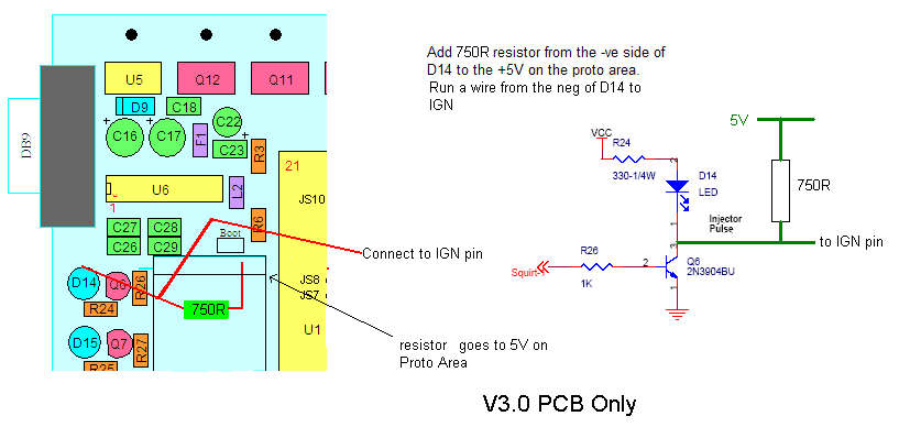
I also threw a NPN on the proto area with the emitter going to ground, collector going to spr3 (with a 1k resistor followed by 5v in-line) and the base going to the bottom of r1 with a in-line 1k resistor. This completes the 4 outputs required for wasted spark COP.
Here is the circuit needed to enable the stock tach to function properly. I've tested this out, and it works great. The relay is used for it's coil only.
View attachment 226052
With the “to tacho” being the input to the vehicles tachometer and the “to selected pin on the pcb” to a spare pin not currently used (js0, js1 etc. selectable in megatune).
The appropriate dwell settings for ls1/ls2 coils can be found here: Megasquirt Sequencer Coils
And the wheel decoder settings can be found here. MSnS Extra Ignition Hardware Manual
I mounted my sensor (as you'll see below) where it was aligned to the number 5 tooth (the 5th tooth CCW from the missing tooth). Whatever tooth you decide to align on, there is a simple spreadsheet found here... http://www.msextra.com/doc/ms1extra/MS_Extra_Software_Manual_files/wheeldecoder.xls ...which allows you to input your sensor location and provide you with the proper settings for megatune/tuner-studio.
Here is what I've found to be the new "easiest" method to get the board up to par. To start off, if you have done the TFI mod to the board...you'll have to undo some of them.
I removed the 1k resistor in D2 and replaced it with a jumper.
I removed the jumper IGBTOUT to IGN.
I removed the 330Ohm resister lead of R26 to IGBTIN
I removed the xg1 to xg2 jumper
I removed the wire from D14 to the IGN jumper
I removed the 1k resistor from s12 to the IGN jumper
I then added all of the VR mods...
I Jumpered VRIN to TACHSELECT
I Jumpered TSEL to VROUT (This may need to be VROUTINV depending on the VR sensor).
Next up was the adding the 5v pull up to the - legs of d14, d15 and d16 as seen here (using a 1k resistor instead of the 750 though)...
I also threw a NPN on the proto area with the emitter going to ground, collector going to spr3 (with a 1k resistor followed by 5v in-line) and the base going to the bottom of r1 with a in-line 1k resistor. This completes the 4 outputs required for wasted spark COP.
Here is the circuit needed to enable the stock tach to function properly. I've tested this out, and it works great. The relay is used for it's coil only.
View attachment 226052
With the “to tacho” being the input to the vehicles tachometer and the “to selected pin on the pcb” to a spare pin not currently used (js0, js1 etc. selectable in megatune).
The appropriate dwell settings for ls1/ls2 coils can be found here: Megasquirt Sequencer Coils
And the wheel decoder settings can be found here. MSnS Extra Ignition Hardware Manual
I mounted my sensor (as you'll see below) where it was aligned to the number 5 tooth (the 5th tooth CCW from the missing tooth). Whatever tooth you decide to align on, there is a simple spreadsheet found here... http://www.msextra.com/doc/ms1extra/MS_Extra_Software_Manual_files/wheeldecoder.xls ...which allows you to input your sensor location and provide you with the proper settings for megatune/tuner-studio.

 I had then spliced into the one that was good....which wreaked havoc. My driver’s side coil bank started firing erratically with the key turned to the on position (not running). Well, I had originally put on a 1uf capacitor on each bank...and when I tied the 12v+ together the extra capacitor was jacking things all to hell. I would have thought it would have been fine...but apparently not!


