
Hi I've owned my 1988 Mustang GT for about a year now. I got it with 97,000 miles on it and only driven it about 110 miles since. It is stock and I've recently been having problems with not having spark and my fuel pump does not prime when I turn the key on. I also have a thick red wire that is between my ignition coil and battery. Heres the whole story. I recently replaced the cars fuel pressure regulator due to a sputter when I would give the car a lot of gas. I drove it after that and although it didn't fix the problem the car ran fine if I babied it. A few weeks later all I did was replace 2 power steering hoses and a windsheild wiper motor. When I finished that I tried to start her up again but it would just turn over and wasn't starting. I pulled a sparkplug out and looked for a spark as I tried to start it but I didn't have a spark, the engine would just turn over. I also didn't smell any fuel after doing this for a while so I listened for the fuel pump to prime when I turned the key like it always does but nothing happened. Even after reseting the inertia switch in the back of the car I had nothing. I tested all the wires I could for voltage. The silinoid had 12.4v (with just key on), the spark plug had 6v (when trying to start the car), and everything that I thought should have voltage I tested and it did so I have power everywhere. I replaced the module on the distributor and brushed off some of the compontents that had a lot of oxidation inside the distributor and the car still had no spark or fuel. Even after replacing the ignition coil and the fuel pump I still had no spark and no fuel pump priming. Now the really confusing part thats been driving me crazy. Their is this thick red wire that I'm not sure if it is anything or not. The previous owner obviesly did a terrible job with the electrical so everything looks bad and unorganized. Could this red wire be something important that is effecting the engine spark and fuel pump? I've tried everything I could think of and I'm completly stumped. I am really desperate for advise and would really appretiat some. Thanks for reading.
You are using an out of date browser. It may not display this or other websites correctly.
You should upgrade or use an alternative browser.
You should upgrade or use an alternative browser.
Electrical Need help please! No spark, Fuel pump not priming, and a mystery wire.
- Thread starter 15reidna
- Start date
- Status
- Not open for further replies.
Illuminator
Active Member
Jrichker posted about troubleshooting these problems on my car here http://www.stangnet.com/mustang-forums/threads/first-5-0-endeavor.866864/#post-8712350 don't know if that helps, but worth a try!
Cranks OK, but No Start Checklist for Fuel Injected Mustangs
A word about this checklist before you start: it is arranged in a specific order to put the most likely failure items first. That will save you time, energy and money. Start at the top of the list and work your way down. Jumping around will possibly cause you to miss just what you need to see to find and fix the problem. Don’t skip any steps because the next step depends on the last step working correctly.
Revised 12-Dec-2011 to replace 10 pin salt & pepper connector graphic.
All text applies to all models unless stated otherwise.
Note: 94-95 specific changes are in red
1.) Remove push on connector (small red/blue wire) from starter solenoid and turn ignition switch to the Run position. Place car in neutral or Park and set the parking brake. Remove the coil wire from distributor & and hold it 3/8” away from the engine block. Jumper the screw to the big bolt on the starter solenoid that has the battery wire connected to it. You should get a nice fat blue spark.
Most of the items are electrical in nature, so a test light, or even better, a voltmeter, is helpful to be sure they have power to them.
No spark, possible failed items in order of their probability:
A.) MSD or Crane ignition box if so equipped
B.) PIP sensor in distributor. The PIP sensor supplies the timing pulse to trigger the TFI and injectors. A failing PIP sensor will sometimes let the engine start if the SPOUT is removed. See paragraph 5A – Using a noid light will tell if the PIP is working by flashing when the engine is cranking.
C.) TFI module: use a test light to check the TFI module. Place one lead of the test light on the red/green wire on the ignition coil connector and the other lead on the dark green/yellow wire on the ignition coil connector. If the TFI is working properly, the test light will flash when the engine is cranked using the ignition switch.
D.) Coil
E.) No EEC or computer power - EEC or computer relay failure
86-93 models only: EEC relay next to computer - look for 12 volts at the fuel injector red wires.
94-95 models only: EEC or PCM power relay in the constant control relay module. Look for 12 volts at the fuel injector red wires.
Both 86-93 and 94-95 models: No 12 volts with the ignition switch in the run position on the fuel injector red wires. The relay has failed or there is no power coming from the ignition switch. Make sure that there is 12 volts on the red/green wire on the coil before replacing the relay.
F.) No EEC or computer power - fuse or fuse link failure
86-93 models only: Fuse links in wiring harness - look for 12 volts at the fuel injector red wires. All the fuse links live in a bundle up near the starter solenoid. Look for a 20 gauge blue fuse link connected to 2 black/orange 14 gauge wires.
94-95 models only: 20 amp EEC fuse in the engine compartment fuse box. Look for 12 volts at the fuel injector red wires.
G.) Ignition switch - look for 12 volts at the ignition coil red/lt green wire. No 12 volts, blown fuse link or faulty ignition switch. Remove the plastic from around the ignition switch and look for 12 volts on the red/green wire on the ignition switch with it in the Run position. No 12 volts and the ignition switch is faulty. If 12 volts is present in the Run position at the ignition switch but not at the coil, then the fuse or fuse link is blown.
Note: fuses or fuse links blow for a reason. Don’t replace either a fuse or fuse link with one with a larger rating than stock. Doing so invites an electrical fire.
Ignition fuse links may be replaced with an inline fuse holder and 5 amp fuse for troubleshooting purposes.
94-95 models only: Check inside fuse panel for fuse #18 blown – 20 amp fuse
H.) Missing or loose computer power ground. The computer has its own dedicated power ground that comes off the ground pigtail on the battery ground wire. Due to it's proximity to the battery, it may become corroded by acid fumes from the battery.
In 86-90 model cars, it is a black cylinder about 2 1/2" long by 1" diameter with a black/lt green wire.
In 91-95 model cars it is a black cylinder about 2 1/2" long by 1" diameter with a black/white wire.
You'll find it up next to the starter solenoid where the wire goes into the wiring harness
I.) Computer. Don’t replace the computer just because you don’t understand how it works. Computers seldom fail, it usually is a sensor or wiring problem that causes the problems.
J.) Bad or missing secondary power ground. It is located between the back of the intake manifold and the driver's side firewall. It supplies ground for the alternator, A/C compressor clutch and other electrical accessories such as the gauges.
K.) Engine fires briefly, but dies immediately when the key is released to the Run position. Crank the engine & when it fires off, pull the small push on connector (red wire) off the starter relay (Looks like it is stuck on a screw). Hold the switch in the crank position: if it continues to run there is a problem with either the ignition switch or TFI module. Check for 12 volts at the red/green wire on the coil with the switch in the Run position. Good 12 volts, then replace the TFI. No 12 volts, replace the ignition switch.
Wiring Diagrams:
See the following website for some help from Tmoss (diagram designer) & Stang&2Birds (website host) for help on 88-95 wiring Mustang FAQ - Engine Information Everyone should bookmark this site.
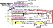
Ignition switch wiring
http://www.veryuseful.com/mustang/tech/engine/images/IgnitionSwitchWiring.gif
Fuel, alternator, A/C and ignition wiring
http://www.veryuseful.com/mustang/tech/engine/images/fuel-alt-links-ign-ac.gif
Complete computer, actuator & sensor wiring diagram for 88-91 Mass Air Mustangs
http://www.veryuseful.com/mustang/tech/engine/images/88-91_5.0_EEC_Wiring_Diagram.gif
Complete computer, actuator & sensor wiring diagram for 91-93 Mass Air Mustangs
http://www.veryuseful.com/mustang/tech/engine/images/91-93_5.0_EEC_Wiring_Diagram.gif
Complete computer, actuator & sensor wiring diagram for 94-95 Mass Air Mustangs
http://www.veryuseful.com/mustang/tech/engine/images/94-95_5.0_EEC_Wiring_Diagram.gif
AutoZone wiring diagrams: You can navigate to the diagrams yourself via Repair Info | AutoZone.com and select the car year, make, model and engine. That will enable you to bring up the wiring diagram for your particular car.
2.) Spark at coil wire, pull #1 plug wire off at the spark plug and check to see spark. No spark, possible failed items in order of their probability: [/b]
A.) Moisture inside distributor – remove cap, dry off & spray with WD40
B.) Distributor cap
C.) Rotor
D.) Spark Plug wires
E.) Coil weak or intermittent - you should see 3/8" fat blue spark with a good coil
3.) Spark at spark plug, but no start.
Next, get a can of starting fluid (ether) from your local auto parts store: costs a $1.30 or so. Then pull the air duct off at the throttle body elbow, open the throttle, and spray the ether in it. Reconnect the air duct and try to start the car. Do not try to start the car without reconnecting the air duct.
Two reasons:
1.) If it backfires, the chance for a serious fire is increased.
2.) On Mass Air cars, the computer needs to measure the MAF flow once the engine starts.
If it starts then, you have a fuel management issue. Continue the checklist with emphasis of fuel related items that follow. If it doesn’t, then it is a computer or timing issue: see Step 4.
Clue – listen for the fuel pump to prime when you first turn the ignition switch on. It should run for 2-4 seconds and shut off. To trick the fuel pump into running, find the EEC test connector and jump the connector in the Upper RH corner to ground. The EEC connector is near the wiper motor and LH hood hinge.

If the relay & inertia switch are OK, you will have power to the pump. Check fuel pressure – remove the cap from the Schrader valve behind the alternator and depress the core. Fuel should squirt out, catch it in a rag. Beware of fire hazard when you do this. In a pinch, you can use a tire pressure gauge to measure the fuel pressure. It may not be completely accurate, but you will have some clue as to how much pressure you have. If you have any doubts about having sufficient fuel flow/pressure, rent a fuel pressure test gauge from the auto parts store. That will tell you for sure if you have adequate fuel pressure.
4.) No fuel pressure, possible failed items in order of their probability:
A.) Tripped inertia switch – Coupe & hatch cars hide it under the plastic trim covering the driver's side taillight. Use the voltmeter or test light to make sure you have power to both sides of the switch
B.) Fuel pump power relay – located under the driver’s seat in most stangs built before 92. On 92 and later model cars it is located below the Mass Air Flow meter. Look for 12 volts at the Pink/Black wire on the fuel pump relay.
C.) Clogged fuel filter
D.) Failed fuel pump
E.) 86-90 models only: Blown fuse link in wiring harness. Look for 12 volts at the Orange/Lt Blue wire on the fuel pump relay.
91-93 models only Blown fuse link in wiring harness. Look for 12 volts at the Pink/Black wire on the fuel pump relay.
The fuse links for all model years 86-93 live in the wiring harness near the starter solenoid.
94-95 models only: 20 amp fuel pump fuse in the engine compartment fuse box. Look for 12 volts at the Dark green/yellow wire on the constant control relay module.
F.) Engine seem to load up on fuel and may have black smoke at the tailpipe. Fuel pressure regulator failed. Remove the vacuum line from the regulator and inspect for fuel escaping while the pump is running. If fuel is coming out the vacuum port, the regulator has failed. Check the regulator vacuum line for fuel too. Disconnect it from the engine and blow air though it. If you find gas, the regulator has failed.
5.) Fuel pressure OK, the injectors are not firing.
A.) The PIP sensor in the distributor tells the computer when to fire the injectors. A failing PIP sensor will sometimes let the engine start if the SPOUT is removed.
A noid light available from any auto parts store, is one way to test the injector circuit to see if the injectors are firing. The noid light plugs into the fuel injector harness in place of any easily accessible injector. Plug it in and try to start the engine: it will flash if the injector is firing.
I like to use an old injector with compressed air applied to the injector where the fuel rail would normally connect. I hook the whole thing up, apply compressed air to the injector and stick it in a paper cup of soapy water. When the engine cranks with the ignition switch on, if the injector fires, it makes bubbles. Cheap if you have the stuff laying around, and works good too.
B.) Pull an injector wire connector off and look for 12 volts on the red wire when the ignition switch is on.
C.) No power, then look for problems with the 10 pin connecter (salt & pepper shakers at the rear of the upper manifold).
See the graphic for the 10 pin connector circuit layout.

The injector power pin is the VPWR pin in the black 10 pin connector.
D.) No power and the 10 pin connections are good: look for broken wiring between the orange/black wire on the EEC relay and the red wire for the 10 pin connectors.
E.) TPS voltage exceeds 3.7 volts with the throttle closed. This will shut off the injectors, since the computer uses this strategy to clear a flooded engine. Use a DVM, a pair of safety pins, and probe the black/white and green wires to measure the TPS voltage.
On a 94-95 Mustang, probe the black/white and grey/white wires to measure the TPS voltage.
It should be .5-.1.0 volts with the key on, engine not running. Note that if the black/white wire (signal ground) has a bad connection, you will get some strange readings. Make a second measurement using the battery post as the ground to eliminate any ground problems. If the readings are different by more than 5%, you may have a high resistance condition in the black/white signal ground circuit.
6.) Spark & fuel pressure OK.
A.) Failed IAB or improperly set base idle (no airflow to start engine). Press the throttle ¼ way down and try to start the car. See the "Surging Idle Checklist for help with all your idle/stall problems.
B.) Failed computer (not very likely)
C.) Engine ignition or cam timing off: only likely if the engine has been worked on recently. If you removed the distributor, there is a good probability that you installed it 180 degrees out of time.
D.) Firing order off: HO & 351 use a different firing order from the non HO engines.
HO & 351W 1-3-7-2-6-5-4-8
Non HO 1-5-4-2-6-3-7-8
E.) No start when hot - Press the throttle to the floor & try starting it if you get this far. If it starts, replace the ECT.
F. ) Engine that has had the heads off or valves adjusted. Do a compression test to make sure the valves are not adjusted too tight. You should have a minimum of 90 PSI on a cold engine.
A word about this checklist before you start: it is arranged in a specific order to put the most likely failure items first. That will save you time, energy and money. Start at the top of the list and work your way down. Jumping around will possibly cause you to miss just what you need to see to find and fix the problem. Don’t skip any steps because the next step depends on the last step working correctly.
Revised 12-Dec-2011 to replace 10 pin salt & pepper connector graphic.
All text applies to all models unless stated otherwise.
Note: 94-95 specific changes are in red
1.) Remove push on connector (small red/blue wire) from starter solenoid and turn ignition switch to the Run position. Place car in neutral or Park and set the parking brake. Remove the coil wire from distributor & and hold it 3/8” away from the engine block. Jumper the screw to the big bolt on the starter solenoid that has the battery wire connected to it. You should get a nice fat blue spark.
Most of the items are electrical in nature, so a test light, or even better, a voltmeter, is helpful to be sure they have power to them.
No spark, possible failed items in order of their probability:
A.) MSD or Crane ignition box if so equipped
B.) PIP sensor in distributor. The PIP sensor supplies the timing pulse to trigger the TFI and injectors. A failing PIP sensor will sometimes let the engine start if the SPOUT is removed. See paragraph 5A – Using a noid light will tell if the PIP is working by flashing when the engine is cranking.
C.) TFI module: use a test light to check the TFI module. Place one lead of the test light on the red/green wire on the ignition coil connector and the other lead on the dark green/yellow wire on the ignition coil connector. If the TFI is working properly, the test light will flash when the engine is cranked using the ignition switch.
D.) Coil
E.) No EEC or computer power - EEC or computer relay failure
86-93 models only: EEC relay next to computer - look for 12 volts at the fuel injector red wires.
94-95 models only: EEC or PCM power relay in the constant control relay module. Look for 12 volts at the fuel injector red wires.
Both 86-93 and 94-95 models: No 12 volts with the ignition switch in the run position on the fuel injector red wires. The relay has failed or there is no power coming from the ignition switch. Make sure that there is 12 volts on the red/green wire on the coil before replacing the relay.
F.) No EEC or computer power - fuse or fuse link failure
86-93 models only: Fuse links in wiring harness - look for 12 volts at the fuel injector red wires. All the fuse links live in a bundle up near the starter solenoid. Look for a 20 gauge blue fuse link connected to 2 black/orange 14 gauge wires.
94-95 models only: 20 amp EEC fuse in the engine compartment fuse box. Look for 12 volts at the fuel injector red wires.
G.) Ignition switch - look for 12 volts at the ignition coil red/lt green wire. No 12 volts, blown fuse link or faulty ignition switch. Remove the plastic from around the ignition switch and look for 12 volts on the red/green wire on the ignition switch with it in the Run position. No 12 volts and the ignition switch is faulty. If 12 volts is present in the Run position at the ignition switch but not at the coil, then the fuse or fuse link is blown.
Note: fuses or fuse links blow for a reason. Don’t replace either a fuse or fuse link with one with a larger rating than stock. Doing so invites an electrical fire.
Ignition fuse links may be replaced with an inline fuse holder and 5 amp fuse for troubleshooting purposes.
94-95 models only: Check inside fuse panel for fuse #18 blown – 20 amp fuse
H.) Missing or loose computer power ground. The computer has its own dedicated power ground that comes off the ground pigtail on the battery ground wire. Due to it's proximity to the battery, it may become corroded by acid fumes from the battery.
In 86-90 model cars, it is a black cylinder about 2 1/2" long by 1" diameter with a black/lt green wire.
In 91-95 model cars it is a black cylinder about 2 1/2" long by 1" diameter with a black/white wire.
You'll find it up next to the starter solenoid where the wire goes into the wiring harness
I.) Computer. Don’t replace the computer just because you don’t understand how it works. Computers seldom fail, it usually is a sensor or wiring problem that causes the problems.
J.) Bad or missing secondary power ground. It is located between the back of the intake manifold and the driver's side firewall. It supplies ground for the alternator, A/C compressor clutch and other electrical accessories such as the gauges.
K.) Engine fires briefly, but dies immediately when the key is released to the Run position. Crank the engine & when it fires off, pull the small push on connector (red wire) off the starter relay (Looks like it is stuck on a screw). Hold the switch in the crank position: if it continues to run there is a problem with either the ignition switch or TFI module. Check for 12 volts at the red/green wire on the coil with the switch in the Run position. Good 12 volts, then replace the TFI. No 12 volts, replace the ignition switch.
Wiring Diagrams:
See the following website for some help from Tmoss (diagram designer) & Stang&2Birds (website host) for help on 88-95 wiring Mustang FAQ - Engine Information Everyone should bookmark this site.
Ignition switch wiring
http://www.veryuseful.com/mustang/tech/engine/images/IgnitionSwitchWiring.gif
Fuel, alternator, A/C and ignition wiring
http://www.veryuseful.com/mustang/tech/engine/images/fuel-alt-links-ign-ac.gif
Complete computer, actuator & sensor wiring diagram for 88-91 Mass Air Mustangs
http://www.veryuseful.com/mustang/tech/engine/images/88-91_5.0_EEC_Wiring_Diagram.gif
Complete computer, actuator & sensor wiring diagram for 91-93 Mass Air Mustangs
http://www.veryuseful.com/mustang/tech/engine/images/91-93_5.0_EEC_Wiring_Diagram.gif
Complete computer, actuator & sensor wiring diagram for 94-95 Mass Air Mustangs
http://www.veryuseful.com/mustang/tech/engine/images/94-95_5.0_EEC_Wiring_Diagram.gif
AutoZone wiring diagrams: You can navigate to the diagrams yourself via Repair Info | AutoZone.com and select the car year, make, model and engine. That will enable you to bring up the wiring diagram for your particular car.
2.) Spark at coil wire, pull #1 plug wire off at the spark plug and check to see spark. No spark, possible failed items in order of their probability: [/b]
A.) Moisture inside distributor – remove cap, dry off & spray with WD40
B.) Distributor cap
C.) Rotor
D.) Spark Plug wires
E.) Coil weak or intermittent - you should see 3/8" fat blue spark with a good coil
3.) Spark at spark plug, but no start.
Next, get a can of starting fluid (ether) from your local auto parts store: costs a $1.30 or so. Then pull the air duct off at the throttle body elbow, open the throttle, and spray the ether in it. Reconnect the air duct and try to start the car. Do not try to start the car without reconnecting the air duct.
Two reasons:
1.) If it backfires, the chance for a serious fire is increased.
2.) On Mass Air cars, the computer needs to measure the MAF flow once the engine starts.
If it starts then, you have a fuel management issue. Continue the checklist with emphasis of fuel related items that follow. If it doesn’t, then it is a computer or timing issue: see Step 4.
Clue – listen for the fuel pump to prime when you first turn the ignition switch on. It should run for 2-4 seconds and shut off. To trick the fuel pump into running, find the EEC test connector and jump the connector in the Upper RH corner to ground. The EEC connector is near the wiper motor and LH hood hinge.
If the relay & inertia switch are OK, you will have power to the pump. Check fuel pressure – remove the cap from the Schrader valve behind the alternator and depress the core. Fuel should squirt out, catch it in a rag. Beware of fire hazard when you do this. In a pinch, you can use a tire pressure gauge to measure the fuel pressure. It may not be completely accurate, but you will have some clue as to how much pressure you have. If you have any doubts about having sufficient fuel flow/pressure, rent a fuel pressure test gauge from the auto parts store. That will tell you for sure if you have adequate fuel pressure.
4.) No fuel pressure, possible failed items in order of their probability:
A.) Tripped inertia switch – Coupe & hatch cars hide it under the plastic trim covering the driver's side taillight. Use the voltmeter or test light to make sure you have power to both sides of the switch
B.) Fuel pump power relay – located under the driver’s seat in most stangs built before 92. On 92 and later model cars it is located below the Mass Air Flow meter. Look for 12 volts at the Pink/Black wire on the fuel pump relay.
C.) Clogged fuel filter
D.) Failed fuel pump
E.) 86-90 models only: Blown fuse link in wiring harness. Look for 12 volts at the Orange/Lt Blue wire on the fuel pump relay.
91-93 models only Blown fuse link in wiring harness. Look for 12 volts at the Pink/Black wire on the fuel pump relay.
The fuse links for all model years 86-93 live in the wiring harness near the starter solenoid.
94-95 models only: 20 amp fuel pump fuse in the engine compartment fuse box. Look for 12 volts at the Dark green/yellow wire on the constant control relay module.
F.) Engine seem to load up on fuel and may have black smoke at the tailpipe. Fuel pressure regulator failed. Remove the vacuum line from the regulator and inspect for fuel escaping while the pump is running. If fuel is coming out the vacuum port, the regulator has failed. Check the regulator vacuum line for fuel too. Disconnect it from the engine and blow air though it. If you find gas, the regulator has failed.
5.) Fuel pressure OK, the injectors are not firing.
A.) The PIP sensor in the distributor tells the computer when to fire the injectors. A failing PIP sensor will sometimes let the engine start if the SPOUT is removed.
A noid light available from any auto parts store, is one way to test the injector circuit to see if the injectors are firing. The noid light plugs into the fuel injector harness in place of any easily accessible injector. Plug it in and try to start the engine: it will flash if the injector is firing.
I like to use an old injector with compressed air applied to the injector where the fuel rail would normally connect. I hook the whole thing up, apply compressed air to the injector and stick it in a paper cup of soapy water. When the engine cranks with the ignition switch on, if the injector fires, it makes bubbles. Cheap if you have the stuff laying around, and works good too.
B.) Pull an injector wire connector off and look for 12 volts on the red wire when the ignition switch is on.
C.) No power, then look for problems with the 10 pin connecter (salt & pepper shakers at the rear of the upper manifold).
See the graphic for the 10 pin connector circuit layout.
The injector power pin is the VPWR pin in the black 10 pin connector.
D.) No power and the 10 pin connections are good: look for broken wiring between the orange/black wire on the EEC relay and the red wire for the 10 pin connectors.
E.) TPS voltage exceeds 3.7 volts with the throttle closed. This will shut off the injectors, since the computer uses this strategy to clear a flooded engine. Use a DVM, a pair of safety pins, and probe the black/white and green wires to measure the TPS voltage.
On a 94-95 Mustang, probe the black/white and grey/white wires to measure the TPS voltage.
It should be .5-.1.0 volts with the key on, engine not running. Note that if the black/white wire (signal ground) has a bad connection, you will get some strange readings. Make a second measurement using the battery post as the ground to eliminate any ground problems. If the readings are different by more than 5%, you may have a high resistance condition in the black/white signal ground circuit.
6.) Spark & fuel pressure OK.
A.) Failed IAB or improperly set base idle (no airflow to start engine). Press the throttle ¼ way down and try to start the car. See the "Surging Idle Checklist for help with all your idle/stall problems.
B.) Failed computer (not very likely)
C.) Engine ignition or cam timing off: only likely if the engine has been worked on recently. If you removed the distributor, there is a good probability that you installed it 180 degrees out of time.
D.) Firing order off: HO & 351 use a different firing order from the non HO engines.
HO & 351W 1-3-7-2-6-5-4-8
Non HO 1-5-4-2-6-3-7-8
E.) No start when hot - Press the throttle to the floor & try starting it if you get this far. If it starts, replace the ECT.
F. ) Engine that has had the heads off or valves adjusted. Do a compression test to make sure the valves are not adjusted too tight. You should have a minimum of 90 PSI on a cold engine.
I just bipassed all of the fusable links and it still does nothing. No fuel pump priming and no spark. So my next quesion is about the fuel pump relay. What exactly does that effect when not working properly? Also will bipassing the links with wire do anything or do I need to buy 4 new fusable links? Thanks for the replys!
What you need to do is follow JR's checklist.
I just bipassed all of the fusable links and it still does nothing. No fuel pump priming and no spark. So my next quesion is about the fuel pump relay. What exactly does that effect when not working properly? Also will bipassing the links with wire do anything or do I need to buy 4 new fusable links? Thanks for the replys!

There are people that successfully fix problems and people who throw parts, time and money at problems.
Which one are you?
Chasing a rabbit when you don't know what the rabbit is supposed to look like is a fruitless task.
I gave you the path to success, and 88LX5.Oh tells you to follow it. How badly do you want to drive the car?
Which one are you?
Chasing a rabbit when you don't know what the rabbit is supposed to look like is a fruitless task.
I gave you the path to success, and 88LX5.Oh tells you to follow it. How badly do you want to drive the car?
Illuminator
Active Member
So should I try fuel pump relay? I tested it with a voltagemeter and didn't get anything from any of the wires when the key was on.
Follow these guys advice.....trust me! Otherwise don't ask for help!

Gabriel Carbajal
Member
- Mar 10, 2013
- 7
- 1
- 14
Shot in the dark but if your ignition switch is anything like the 93s they fall apart. You will loose power to some circuits.
Sent from my Galaxy Nexus using Tapatalk 2
Sent from my Galaxy Nexus using Tapatalk 2
What step in the checklist are you at? Start at the top and work your way down, don't skip any steps or you might miss the very thing that will lead to to the correct fix.
Illuminator
Active Member
Didn't mean to come off like an ass in fact tried repeatedly to edit above post but locked out for some reason....anyways the point I was making is what was said above. I went for years w/o fixing electrical issue just by not following the tech or wanting to accept the diagnosis.
:What step in the checklist are you at? Start at the top and work your way down, don't skip any steps or you might miss the very thing that will lead to to the correct fix.
Yep. It can be a pain and require reading several times. But you must do it. Make print outs and check off each step as you go. This is not your grandpa's Oldsmobile. The testing steps are longer and the distributor is in the wrong place.
I went to step 4 since I don't have any fuel pressure and my fuel pump isn't priming. The previous owner bipassed the inertia switch so that's useless at the moment, I just replaced the fuel pump relay, I also replaced the fuel pump and the fuel filter, so where do I go from here?
The no spark checklist talks about a EEC and PIP? Could those affect fuel pumps as well as not having spark?
The no spark checklist talks about a EEC and PIP? Could those affect fuel pumps as well as not having spark?
")
You're 17 - I should have figured that - still haven't gotten over the teenage rebellion against people trying to tell you what to do. You are back in school and I am your shop teacher, so listen closely....
The idea behind the checklist is to eliminate the things that do work so that all that is left is what doesn't work. IF you follow the checklist, the list of things suspect shrinks dramatically. What's left is not hard to test and diagnose so you don't spend money and time with no positive results.
Back up to 1-C: Do you have 12 volts on the red/green coil wire with the ignition switch in the Run position?
No, then you have a bad ignition switch or a blown fuse link in the ignition coil red/green power feed
Yes: Good 12 volts on the red/green coil wire with the ignition switch in the Run position. Go to the next step.
1-D: Coil since you are not getting fuel pressure, the coil has no effect on your current problem. Got to the next step.
1-E: Do you have 12 volts on the red injector wiring with the ignition switch in the Run position?
No - Then you have an ECC (computer) relay or fuse link problem. The red/green wire actuates the EEC relay causing it to close and provide power to the computer, fuel pump inertia switch, fuel injectors and some other items.
If you can actually read the diagrams, they will shorten your troubleshooting time considerably. Click on the diagrams to enlarge them for easier viewing.
Diagrams courtesy of Tmoss & Stang&2birds


See the following website for some help from Tmoss (diagram designer) & Stang&2Birds (website host) for help on 88-95 wiring http://www.veryuseful.com/mustang/tech/engine/ Everyone should bookmark this site.
Ignition switch wiring
http://www.veryuseful.com/mustang/tech/engine/images/IgnitionSwitchWiring.gif
Fuel, alternator, A/C and ignition wiring
http://www.veryuseful.com/mustang/tech/engine/images/fuel-alt-links-ign-ac.gif
Complete computer, actuator & sensor wiring diagram for 88-91 Mass Air Mustangs
http://www.veryuseful.com/mustang/tech/engine/images/88-91_5.0_EEC_Wiring_Diagram.gif
Complete computer, actuator & sensor wiring diagram for 91-93 Mass Air Mustangs
http://www.veryuseful.com/mustang/tech/engine/images/91-93_5.0_EEC_Wiring_Diagram.gif
Vacuum diagram 89-93 Mustangs
http://www.veryuseful.com/mustang/tech/engine/images/mustangFoxFordVacuumDiagram.jpg
HVAC vacuum diagram
http://www.veryuseful.com/mustang/tech/engine/images/Mustang_AC_heat_vacuum_controls.gif
TFI module differences & pin out
http://www.veryuseful.com/mustang/tech/engine/images/TFI_5.0_comparison.gif
Fuse box layout
http://www.veryuseful.com/mustang/tech/engine/images/MustangFuseBox.gif
87-92 power window wiring
http://www.veryuseful.com/mustang/tech/engine/images/mustang87-92 PowerWindowWiring.gif
93 power window wiring
http://www.veryuseful.com/mustang/tech/engine/images/mustang93PowerWindows.gif
The idea behind the checklist is to eliminate the things that do work so that all that is left is what doesn't work. IF you follow the checklist, the list of things suspect shrinks dramatically. What's left is not hard to test and diagnose so you don't spend money and time with no positive results.
Back up to 1-C: Do you have 12 volts on the red/green coil wire with the ignition switch in the Run position?
No, then you have a bad ignition switch or a blown fuse link in the ignition coil red/green power feed
Yes: Good 12 volts on the red/green coil wire with the ignition switch in the Run position. Go to the next step.
1-D: Coil since you are not getting fuel pressure, the coil has no effect on your current problem. Got to the next step.
1-E: Do you have 12 volts on the red injector wiring with the ignition switch in the Run position?
No - Then you have an ECC (computer) relay or fuse link problem. The red/green wire actuates the EEC relay causing it to close and provide power to the computer, fuel pump inertia switch, fuel injectors and some other items.
If you can actually read the diagrams, they will shorten your troubleshooting time considerably. Click on the diagrams to enlarge them for easier viewing.
Diagrams courtesy of Tmoss & Stang&2birds
See the following website for some help from Tmoss (diagram designer) & Stang&2Birds (website host) for help on 88-95 wiring http://www.veryuseful.com/mustang/tech/engine/ Everyone should bookmark this site.
Ignition switch wiring
http://www.veryuseful.com/mustang/tech/engine/images/IgnitionSwitchWiring.gif
Fuel, alternator, A/C and ignition wiring
http://www.veryuseful.com/mustang/tech/engine/images/fuel-alt-links-ign-ac.gif
Complete computer, actuator & sensor wiring diagram for 88-91 Mass Air Mustangs
http://www.veryuseful.com/mustang/tech/engine/images/88-91_5.0_EEC_Wiring_Diagram.gif
Complete computer, actuator & sensor wiring diagram for 91-93 Mass Air Mustangs
http://www.veryuseful.com/mustang/tech/engine/images/91-93_5.0_EEC_Wiring_Diagram.gif
Vacuum diagram 89-93 Mustangs
http://www.veryuseful.com/mustang/tech/engine/images/mustangFoxFordVacuumDiagram.jpg
HVAC vacuum diagram
http://www.veryuseful.com/mustang/tech/engine/images/Mustang_AC_heat_vacuum_controls.gif
TFI module differences & pin out
http://www.veryuseful.com/mustang/tech/engine/images/TFI_5.0_comparison.gif
Fuse box layout
http://www.veryuseful.com/mustang/tech/engine/images/MustangFuseBox.gif
87-92 power window wiring
http://www.veryuseful.com/mustang/tech/engine/images/mustang87-92 PowerWindowWiring.gif
93 power window wiring
http://www.veryuseful.com/mustang/tech/engine/images/mustang93PowerWindows.gif
Attachments
-
 88-91_5.0_EEC_Wiring_Diagram.gif168.5 KB · Views: 1,767
 -
 88-91_5.0_EEC_Wiring_Diagram.gif168.5 KB · Views: 492
 -
 IgnitionSwitchWiring.gif10.1 KB · Views: 4,077
 -
 IgnitionSwitchWiring.gif10.1 KB · Views: 1,686
 -
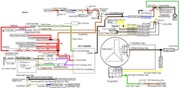 fuel-alt-links-ign-ac.gif83.1 KB · Views: 2,762
 -
 fuel-alt-links-ign-ac.gif83.1 KB · Views: 528
You're 17 - I should have figured that - still haven't gotten over the teenage rebellion against people trying to tell you what to do. You are back in school and I am your shop teacher, so listen closely....
Quote]
I call age discrimination! If his excuse is rebellion, do the rest of us get to claim stupidity, until we can claim senility? Actually, that sounds better than not having the reading comprehension and skills to understand the long steps. As far as the OP, he may have never worked on a computer this primitive. Let's really confuse him and have him set the points on a 68 next! The two lines on the advance canister will make most anyone wonder what Ford was thinking.
Alright I pulled the steering column cover off and tested the red/green wire in the igntion switch and did not get anything from it with the key in the run position. Does the ignition switch affect the fuel pump not working? I've already replaced the fuel filter, fuel pump, fuel pump relay, eec relay, and the inertia switch is bipassed so if the ignition switch isn't the problem then I don't know where I'll go from there. Also, apparently their is supposed to be a EEC computer test plug near the wiper motor but I can't find any plugs that look like the diagram in my car. Any advice/ideas?
Alright I pulled the steering column cover off and tested the red/green wire in the igntion switch and did not get anything from it with the key in the run position. Does the ignition switch affect the fuel pump not working? I've already replaced the fuel filter, fuel pump, fuel pump relay, eec relay, and the inertia switch is bipassed so if the ignition switch isn't the problem then I don't know where I'll go from there. Also, apparently their is supposed to be a EEC computer test plug near the wiper motor but I can't find any plugs that look like the diagram in my car. Any advice/ideas?
No power on the red/green wire with the ignition switch in the Run position, means no power to the EEC relay.
No Power to the EEC relay, means no power to the inertia switch.
No power to the inertia switch means no power to the fuel pump relay coil.
No power to the fuel pump relay coil means the relay contacts won't close.
If the relay contacts don't close, the fuel pump will not run.
In simple terms, no power on the red/green wire with the ignition switch in the Run position means nothing works normally. Fix that and you will probably fix all the other problems. They are symptoms of the problem, not the cause of the problem.
The computer diagnostic connector may still have the original dust cover on it, which may still be mounted on the driver side inner fender well by the brake booster. Don't worry about it until you have power for the EEC relay and the fuel pump relay. STAY focused on the current path and you will find and fix the problem.
- Status
- Not open for further replies.
Similar threads
- Replies
- 8
- Views
- 254
- Replies
- 10
- Views
- 304
- Replies
- 7
- Views
- 305
- Replies
- 51
- Views
- 1K
- Replies
- 6
- Views
- 122