
You are using an out of date browser. It may not display this or other websites correctly.
You should upgrade or use an alternative browser.
You should upgrade or use an alternative browser.
Progress Thread Nicholase "lights out" build- TKX install
- Thread starter nicholase
- Start date
Yeah, the list is a little nuts. It helps keep me on track and budget. The more detailed I make it the more stuff I realize I need. It really helps. Then I just check them off as I go.
I went through my bolts today. Missing TB studs. Ordered them and some other stuff.

Also got the new Trick Flow Intake, Edelbrock waterpump, blower mount bracket, original t-stat housing, and original timing cover painted. I always love the look of fresh cast aluminum but it doesn't look good for long. I used the same prep, and primer as the block and oil pan. I top coated it with Eastwood 2k Auma Blast. It's supposed yo give that new cast aluminum look. I'd say it's pretty close. Hopefully this will hold up. It's the same catalyzed two part paint I used on the block. It's said to be very oil / gas / cleaner resistant. On Eastwoods demo video they wipe it down with acetone and it hold up.
It's all dry. Just pulled off the tape:

I had a hard time dropping 300+ bucks on a water pump. But from everything I've read it's the most reliable out there. It sure seems solid.
I went through my bolts today. Missing TB studs. Ordered them and some other stuff.
Also got the new Trick Flow Intake, Edelbrock waterpump, blower mount bracket, original t-stat housing, and original timing cover painted. I always love the look of fresh cast aluminum but it doesn't look good for long. I used the same prep, and primer as the block and oil pan. I top coated it with Eastwood 2k Auma Blast. It's supposed yo give that new cast aluminum look. I'd say it's pretty close. Hopefully this will hold up. It's the same catalyzed two part paint I used on the block. It's said to be very oil / gas / cleaner resistant. On Eastwoods demo video they wipe it down with acetone and it hold up.
It's all dry. Just pulled off the tape:
I had a hard time dropping 300+ bucks on a water pump. But from everything I've read it's the most reliable out there. It sure seems solid.

Did you read it in one breath?Now THAT is a list!

Installing the ProM is still a ways out. But I'm planning parts of it. I went with the crank trigger option. It essentially removes the need for a working TFI moduel and a quality PIP. So getting away from that was the reasoning behind that option.
It comes with a trigger wheel that mounts between the harmonic balancer and the front pulley. However that pushes the pulley out the thickness of the wheel. They include a shim for the WP pulley to offset it the same amount. So either I have to live with the rest of the accessory drive out of line or shim all that out. I dont want belt issues or try amd shim out all that stuff. So....
I came up with a work around. I'm using a new Ford 50oz balancer. Heres a pic of the balancer , trigger wheel and pulley.

When you put the trigger wheel on it pushes out the pulley. There also isn't hardly any snout left sticking out to center the pulley.

So I took the balancer to a local machine shop. I have the bolt circle turned down the thickness of the trigger wheel.
Before:

After:

Now the trigger wheel slides on and won't kick out the pulley any. It also leaves the correct snout protruding to center the pulley.


Here's the mount that holds the sensor. It secures to the two front oil pan bolts as well as one of the front cover bolts. The two raises circles below the ProM logo are for the oil pan bolts to pass through.

To install it calls to cut off the portion of the oil pan rails that would be under the bolts. If you don't the bracket will sit too low and not line up for the front cover bolt.
Left side of pic shows the two raised oil pan bolt holes. Above them is the hole for the front cover bolt.

I don't want to cut my oil pan rails. So while I was at the machine shop i had them machine down the two circles the thickness of the oil pan rail.

Now I can use it along with my pan rails and the front cover bolts hole lines up perfectly.
I did test fit it and it's gonna work sweet. This whole thing would go faster if I wasn't so OCD.....
It comes with a trigger wheel that mounts between the harmonic balancer and the front pulley. However that pushes the pulley out the thickness of the wheel. They include a shim for the WP pulley to offset it the same amount. So either I have to live with the rest of the accessory drive out of line or shim all that out. I dont want belt issues or try amd shim out all that stuff. So....
I came up with a work around. I'm using a new Ford 50oz balancer. Heres a pic of the balancer , trigger wheel and pulley.
When you put the trigger wheel on it pushes out the pulley. There also isn't hardly any snout left sticking out to center the pulley.
So I took the balancer to a local machine shop. I have the bolt circle turned down the thickness of the trigger wheel.
Before:
After:
Now the trigger wheel slides on and won't kick out the pulley any. It also leaves the correct snout protruding to center the pulley.
Here's the mount that holds the sensor. It secures to the two front oil pan bolts as well as one of the front cover bolts. The two raises circles below the ProM logo are for the oil pan bolts to pass through.
To install it calls to cut off the portion of the oil pan rails that would be under the bolts. If you don't the bracket will sit too low and not line up for the front cover bolt.
Left side of pic shows the two raised oil pan bolt holes. Above them is the hole for the front cover bolt.
I don't want to cut my oil pan rails. So while I was at the machine shop i had them machine down the two circles the thickness of the oil pan rail.
Now I can use it along with my pan rails and the front cover bolts hole lines up perfectly.
I did test fit it and it's gonna work sweet. This whole thing would go faster if I wasn't so OCD.....
Attachments

Last edited:
gkomo
now i can hopefully expect to receive the shaft
Smart moves, wonder why the ProM people didn’t just do it that way from the get-go.

Today I installed the oil pump. I'm using a Melling 10687 cast iron replacement pump. This is a standard pressure, standard volume pump. It's the revised high performance version of the M68. It has a better more rugged internal design. It does come with a spring you can change to increase oil pressure but I left it stock.
I'm also installing a new Ford Performance stock replacement oil pan and pickup tube. I painted the oil pan with the block last weekend. I'm using ARP oil pump bolts and driveshaft.
I can confirm the Melling 10687 does fit the Ford Performance pan with no need to clearance anything. Stock aluminum pump in pictue to compare.

With the engine upside-down on the stand I checked the depth of the pickup to oil pan bottom. I used a peice of modeling clay on the pickup to see the distance. I made some adjustments (bent) to the pickup mounting tab until I was within spec.

I also took the opportunity to check the torque of the main caps and rod caps while I was in there.
I'm also installing a new Ford Performance stock replacement oil pan and pickup tube. I painted the oil pan with the block last weekend. I'm using ARP oil pump bolts and driveshaft.
I can confirm the Melling 10687 does fit the Ford Performance pan with no need to clearance anything. Stock aluminum pump in pictue to compare.
With the engine upside-down on the stand I checked the depth of the pickup to oil pan bottom. I used a peice of modeling clay on the pickup to see the distance. I made some adjustments (bent) to the pickup mounting tab until I was within spec.
I also took the opportunity to check the torque of the main caps and rod caps while I was in there.
89ripper
Founding Member
Love your methodical approach and attention to detail. Been a joy following along.
Getting the valve train stuff ready. I'm using the Ford performance M-6253-A50 spyder plate and dogbones kit, the Ford Motorsporst SVO M-6268-A302 timing set and Trick Flow TFS-51403001 cam.
The top end kit did come with a TF branded timing set. It used a bronze thrust washer (different than OEM design), and mentioned needing to countersink the thrust plate for the hold down bolt heads. I wasn't cool with that so I grabbed the Ford set.
For lifters I'm using the Ford Performance M-6500-R302H. These are the versions with the upgraded internals and are designated by the "H". I was a bit concerned because the description mentions they have a 1/16" longer body than the non "H" OEM replacement version and the heads may need to be removed to remove the lifters.
To check I test fit them with the heads. I can confirm the "H" version lifters can be installed / removed with trick flow 170 heads. The heads have a recess machined in the overhang. It's just enough room. I didn't have a head gasket on during this check. So there will plenty of room to replace them if the time ever comes.
The lifter body is a bit longer, however the recess for the pushrod is deeper. I used a dial indicator and jig to measure the total length of the factory lifter and pushrod (roller tip to pushrod tip) and new lifters with the same pushrod in the same manner They are in fact the same overall length. Actually I measure .005 shorter for the new lifters. I'll still run through the pushrod length and geometry tests later on, but this should be fine.
Last edited:
I run the same lifters and can verify they will not collapse over 6500 rpm.


gkomo
now i can hopefully expect to receive the shaft
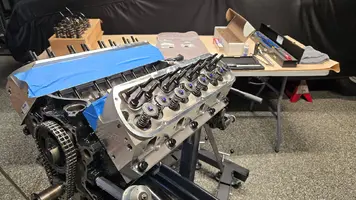
Today I installed the lifters. I primed the oil system with a drill and oil pump drive adapter as a precaution. I'm pretty sure 99% of new lifter failures are related to debris getting stuck in them on the first start up.To make sure no junk gets in the new lifters I have a priming procedure that I haven't seem anyone else ever do. It works real good and only take a few extra minutes.
The oil feeds the lifter galleries from the back of the engine to the front. Without any lifters installed oil just dumps out from the rear lifter feed through the empty lifter bore hole.
With that in mind I start by priming the oil pump with no lifters in. After a few seconds you can see the oil dumping out of rear lifter feed hole. This clears out the passages between the pump and lifter gallery. Let that flow for a bit to flush anything out. Wipe out the lifter bore and install the rearward most lifter on each bank and prime again. Oil will now flow around and through the two rear most lifters and through the next passageway. Then oil dumps out in the next empty lifter hole. Let it flush for a bit, wipe out, then install the next two lifters. And so on. As more lifter are installed oil pressure will get higher and the drill will feel more resistance. This way you are always flushing any possible debris out the empty lifter hole first and not into your new lifter.
A few installed and primed

A few more

When all the lifters in I pulled the pan with the oil still in it and took a look. I didn't see anything, so thats good. I just had the pan on with a few bolts and no gasket. I gave the rotating assemble a wipe down and cleaned out the pan. Should be good to go now.
The oil feeds the lifter galleries from the back of the engine to the front. Without any lifters installed oil just dumps out from the rear lifter feed through the empty lifter bore hole.
With that in mind I start by priming the oil pump with no lifters in. After a few seconds you can see the oil dumping out of rear lifter feed hole. This clears out the passages between the pump and lifter gallery. Let that flow for a bit to flush anything out. Wipe out the lifter bore and install the rearward most lifter on each bank and prime again. Oil will now flow around and through the two rear most lifters and through the next passageway. Then oil dumps out in the next empty lifter hole. Let it flush for a bit, wipe out, then install the next two lifters. And so on. As more lifter are installed oil pressure will get higher and the drill will feel more resistance. This way you are always flushing any possible debris out the empty lifter hole first and not into your new lifter.
A few installed and primed
A few more
When all the lifters in I pulled the pan with the oil still in it and took a look. I didn't see anything, so thats good. I just had the pan on with a few bolts and no gasket. I gave the rotating assemble a wipe down and cleaned out the pan. Should be good to go now.
With that behind me I moved onto the valve train setup. Here's the stuff going in. The Motorsport timing set comes with a new thrust plate. I used ARP thrust plate bolts, ARP cam retaining bolt and washer, ARP balancer bolt and washer.

I checked the camshaft end play with a dial indicator. Came is at .003 which falls well between the .001"min - .007"max.

Then I checked the degree of the cam. The Motorsport timing set has 9 way keyway for 2° adjustments. I started with the 0° straight up marks. Thats where i want it.
Finding true TDC

Then finding the centerline of the cam lobe

After a little bit of math (or maths if you're brittish) my measurements matched the cam card intake/ exhaust centerline exactly. So in my case straight up is actually straight up.

With all that known I disassembled the timing chain and prepared it for final assembley. I cleaned and dried all the threads for blue locktite. Then torqued everything down. Also clean and dry for the sprocket to cam face is how I was taught. I mentioned I worked at a Ford dealer in the early 90's. I remember having a cam sprocket shear the dowel on a job i did. The shop foreman told me the dowel is just to align the cam, not to hold it in place. And was particularly clear that I'll always clean and dry the cam face, sprocket and any bolt holes then use locktite on the treads. Old timer. Very clear with alot of F words lol. It always stuck with me.

I checked the camshaft end play with a dial indicator. Came is at .003 which falls well between the .001"min - .007"max.
Then I checked the degree of the cam. The Motorsport timing set has 9 way keyway for 2° adjustments. I started with the 0° straight up marks. Thats where i want it.
Finding true TDC
Then finding the centerline of the cam lobe
After a little bit of math (or maths if you're brittish) my measurements matched the cam card intake/ exhaust centerline exactly. So in my case straight up is actually straight up.
With all that known I disassembled the timing chain and prepared it for final assembley. I cleaned and dried all the threads for blue locktite. Then torqued everything down. Also clean and dry for the sprocket to cam face is how I was taught. I mentioned I worked at a Ford dealer in the early 90's. I remember having a cam sprocket shear the dowel on a job i did. The shop foreman told me the dowel is just to align the cam, not to hold it in place. And was particularly clear that I'll always clean and dry the cam face, sprocket and any bolt holes then use locktite on the treads. Old timer. Very clear with alot of F words lol. It always stuck with me.
Engine Bolt list:
[ ] ARP Head studs 154-4201
[ ] ARP balancer bolt 150-2501
[ ] ARP oil pan bolts 254-1804
[ ] ARP Flywheel bolts 200-2802
[ ] ARP Intake stud kit 354-2103
[ ] ARP oil pump drive shaft 154-7904
[ ] ARP cam thrust plate bolts 250-1001
[ ] ARP cam sprocket bolt 245-1001
[ ] ARP Head studs 154-4201
[ ] ARP balancer bolt 150-2501
[ ] ARP oil pan bolts 254-1804
[ ] ARP Flywheel bolts 200-2802
[ ] ARP Intake stud kit 354-2103
[ ] ARP oil pump drive shaft 154-7904
[ ] ARP cam thrust plate bolts 250-1001
[ ] ARP cam sprocket bolt 245-1001
I'm not, I'm Texan... but your work is outstanding.(or maths if you're brittish)
I started on the heads and valvtrain.
I noticed Trick Flow makes a nice head dowel. It's a solid machined dowel. I like that it has smooth edges so I don't have to worry much about accidentally scratching the head surface on them. They also seem much more accurate than the split style.

I removed all the valve springs on both heads and installed checker springs. Some blue tape on the deck surface to protect from scratches.

Heads mounted up temporarily. Installed the PR guide plates and rocker studs. Then went through the geometry tests. TF suggests roller tip travel less than .080". I measured between .048"-.060". Well centered on the valves. With my dial indicator I measured them for center at half lift as TF suggests to do. That was perfect. I didn't even need to use my adjustable pushrod. Just used the ones that came in the kit. Also checked PV clearance and it was good as expected.


I pulled the heads back off and got the springs swapped back. Got em all ready to install with fresh gaskets and studs.
I noticed Trick Flow makes a nice head dowel. It's a solid machined dowel. I like that it has smooth edges so I don't have to worry much about accidentally scratching the head surface on them. They also seem much more accurate than the split style.
I removed all the valve springs on both heads and installed checker springs. Some blue tape on the deck surface to protect from scratches.
Heads mounted up temporarily. Installed the PR guide plates and rocker studs. Then went through the geometry tests. TF suggests roller tip travel less than .080". I measured between .048"-.060". Well centered on the valves. With my dial indicator I measured them for center at half lift as TF suggests to do. That was perfect. I didn't even need to use my adjustable pushrod. Just used the ones that came in the kit. Also checked PV clearance and it was good as expected.
I pulled the heads back off and got the springs swapped back. Got em all ready to install with fresh gaskets and studs.
Attachments
Last edited:
With the heads back off I spun the engine around on my stand. I want to be able to check the rear main seal for a leak before I get the engine back in the car. I polished the crank journal, then popped in a new seal.

I installed some more stuff from Ford Performamce. A new engine plate, a billet steel flywheel, and dowels. Secured with ARP bolts.


With all that mounted up I spun the engine back around on the stand. Now I can prime the oil pump and make sure there are no leaks.
I installed some more stuff from Ford Performamce. A new engine plate, a billet steel flywheel, and dowels. Secured with ARP bolts.
With all that mounted up I spun the engine back around on the stand. Now I can prime the oil pump and make sure there are no leaks.
gkomo
now i can hopefully expect to receive the shaft
Also worth mentioning to possibly save someone else some grief, originally i ordered the black engine spacer plate from LMR https://lmr.com/item/LRS-7007R/mustang-bellhousing-spacer-plate-7995-50
It's not properly made. At least the one i got isn't. When installed on the engine dowel pins it's flexed so much it bows out and hits the flywheel. I thought the black powder coating would be nice and it says that it's made in the USA, although there's no indication of such on it. I'll be sending it back. The Ford Performance spacer plate fit perfectly and is stamped made in USA.
These things are important because they index the starter properly to the flywheel.
Put a mechanical pressure guage on to check the new oil pump

Lots of priming and spinning the crank around with a wrench. So far rear main is bone dry. While not a guarantee, it's is a good indicator.
I'll keep an eye on it until the engine goes back in.
Lots of priming and spinning the crank around with a wrench. So far rear main is bone dry. While not a guarantee, it's is a good indicator.
I'll keep an eye on it until the engine goes back in.
Similar threads
What's it Worth?
1997 Cobra, a ton of mods and restoration
- Replies
- 2
- Views
- 78
- Replies
- 4
- Views
- 464
- Replies
- 21
- Views
- 4K
- Replies
- 0
- Views
- 263
- Replies
- 17
- Views
- 4K