
I've tried everything with this car but I can't give up because I love it. I've had a real running rich problem since I got it. It has no smog pump, egr system is gone, no MAF sensor it's a speed density setup. It's also a 5 speed manual. Turns out I had a computer out of 80's crown Victoria which is a batch fire computer, not right for my car. So I get a DA1 which is what's supposed to be in my car.It won't start and run. I checked and rechecked firing order, timing, spark,fuel pressure, TPS and won't run on its own. I don't know what to do now so I put other computer back in. PLEASE HELP !!!
You are using an out of date browser. It may not display this or other websites correctly.
You should upgrade or use an alternative browser.
You should upgrade or use an alternative browser.
Please help 88 5.0 mustang gt.
- Thread starter Bobby from 757
- Start date
First step is to verify what the engine uses for a firing order. Don't take for granted that it is the HO firing order just because it is in a Mustang or has a HO plate on top of the intake manifold. The camshaft inside the engine is what determines the firing order.
This doesn’t prove that the block is a HO block. Some trucks evidently use a HO firing order with a low lift cam (this will result in less than the desired HP output). However, it will definitely prove that a block can’t be HO because the firing order is wrong.
Remove the #1 & #3 spark plugs. Put your finger in #1 spark plug hole. Crank the engine over until you feel compression on #1 cylinder. Slowly turn the engine until the TDC mark and the timing pointer line up. Mark TDC on the balancer with chalk or paint. Put your finger in #3 spark plug hole and crank the engine 90 degrees. You should feel pressure trying to blow past your finger. If you do not feel pressure, repeat the process again. If you feel pressure, it is a HO engine.
No pressure the second time, remove spark plug #5. Put your finger in #1 spark plug hole. Crank the engine over until you feel compression on #1 cylinder. Put your finger in #5 spark plug hole and crank the engine 90 degrees. If you feel pressure now, the engine is not a HO model, no matter what it says on the engine.
Using a small carpenter or machinist square to mark the harmonic balancer off into 90 degree sections may be helpful here.
A 15/16 deep socket & breaker bar or ratchet may be used to turn the engine.
The HO firing order is 1-3-7-2-6-5-4-8.
Non HO firing order is 1-5-4-2-6-3-7-8
Do an end to the injector wring test to make sure that the injectors are properly sequenced for a HO engine and computer
Disconnect the main connector from the computer and pull it down so that you have good access to the computer side of the connector.
Place one voltmeter lead in pin 40 or 60 - they are both the main computer power ground. This lead does not change for any of the tests
Disconnect all the injector connectors from the injectors.
You will re-connect them one at a time to do the testing. Once you have checked an injector lead, disconnect it before testing the next injector. Fail to do this and you will get incorrect results
Turn the ignition switch to Run
Check pins 37 & 57; you should see 12 volts.
Computer wiring harness connector, wire side

Computer wiring harness connector, computer side

Here are the HO injector wires that are different; check to see that you have 12 volts on them one at a time.
Connect injector #3, look for 12 volts on pin 12 on the computer. Disconnect the injector connector from the injector before testing the next wire.
Connect injector #7, look for 12 volts on pin 42 on the computer. Disconnect the injector connector from the injector before testing the next wire.
Connect injector #5, look for 12 volts on pin 14 on the computer. Disconnect the injector connector from the injector before testing the next wire.
Connect injector #4. look for 12 volts on pin 13 on the computer. You are finished now and can reconnect all the injector connectors to the injectors.
Dump codes sticky
Look at the top of the 5.0 Tech forum where the sticky threads are posted. One of them is how to dump the computer codes. Codes may be present even if the CEL (Check Engine Light) isn’t on. You don’t need a code reader or scanner – all you need is a paper clip, or if your lady friend has a hair pin, that will do the job.
I highly suggest that you read it and follow the instructions to dump the codes. http://www.stangnet.com/mustang-forums/threads/how-to-pull-codes-from-eec4.889006/[/img]
This doesn’t prove that the block is a HO block. Some trucks evidently use a HO firing order with a low lift cam (this will result in less than the desired HP output). However, it will definitely prove that a block can’t be HO because the firing order is wrong.
Remove the #1 & #3 spark plugs. Put your finger in #1 spark plug hole. Crank the engine over until you feel compression on #1 cylinder. Slowly turn the engine until the TDC mark and the timing pointer line up. Mark TDC on the balancer with chalk or paint. Put your finger in #3 spark plug hole and crank the engine 90 degrees. You should feel pressure trying to blow past your finger. If you do not feel pressure, repeat the process again. If you feel pressure, it is a HO engine.
No pressure the second time, remove spark plug #5. Put your finger in #1 spark plug hole. Crank the engine over until you feel compression on #1 cylinder. Put your finger in #5 spark plug hole and crank the engine 90 degrees. If you feel pressure now, the engine is not a HO model, no matter what it says on the engine.
Using a small carpenter or machinist square to mark the harmonic balancer off into 90 degree sections may be helpful here.
A 15/16 deep socket & breaker bar or ratchet may be used to turn the engine.
The HO firing order is 1-3-7-2-6-5-4-8.
Non HO firing order is 1-5-4-2-6-3-7-8
Do an end to the injector wring test to make sure that the injectors are properly sequenced for a HO engine and computer
Disconnect the main connector from the computer and pull it down so that you have good access to the computer side of the connector.
Place one voltmeter lead in pin 40 or 60 - they are both the main computer power ground. This lead does not change for any of the tests
Disconnect all the injector connectors from the injectors.
You will re-connect them one at a time to do the testing. Once you have checked an injector lead, disconnect it before testing the next injector. Fail to do this and you will get incorrect results
Turn the ignition switch to Run
Check pins 37 & 57; you should see 12 volts.
Computer wiring harness connector, wire side
Computer wiring harness connector, computer side
Here are the HO injector wires that are different; check to see that you have 12 volts on them one at a time.
Connect injector #3, look for 12 volts on pin 12 on the computer. Disconnect the injector connector from the injector before testing the next wire.
Connect injector #7, look for 12 volts on pin 42 on the computer. Disconnect the injector connector from the injector before testing the next wire.
Connect injector #5, look for 12 volts on pin 14 on the computer. Disconnect the injector connector from the injector before testing the next wire.
Connect injector #4. look for 12 volts on pin 13 on the computer. You are finished now and can reconnect all the injector connectors to the injectors.
Dump codes sticky
Look at the top of the 5.0 Tech forum where the sticky threads are posted. One of them is how to dump the computer codes. Codes may be present even if the CEL (Check Engine Light) isn’t on. You don’t need a code reader or scanner – all you need is a paper clip, or if your lady friend has a hair pin, that will do the job.
I highly suggest that you read it and follow the instructions to dump the codes. http://www.stangnet.com/mustang-forums/threads/how-to-pull-codes-from-eec4.889006/[/img]
Last edited:
Blown88GT
Founding Member
I still have my DA1 stored away & that is the correct one for a non-California '88. '88's were speed density (no MAF).I've tried everything with this car but I can't give up because I love it. I've had a real running rich problem since I got it. It has no smog pump, egr system is gone, no MAF sensor it's a speed density setup. It's also a 5 speed manual. Turns out I had a computer out of 80's crown Victoria which is a batch fire computer, not right for my car. So I get a DA1 which is what's supposed to be in my car.It won't start and run. I checked and rechecked firing order, timing, spark,fuel pressure, TPS and won't run on its own. I don't know what to do now so I put other computer back in. PLEASE HELP !!!
So I did the test it is HO Motor. Disconnected battery, pulled spout connector ,changed computer. Started it up and it ran on its own. Got timing light set to 12degrees. Shut off put spout connector back in and its running good. I get to looking around and map sensor unplugged. What does this mean ? I have the DA1 ecm in car not the DK17.I still have my DA1 stored away & that is the correct one for a non-California '88. '88's were speed density (no MAF).
So I did the test it is HO Motor. Disconnected battery, pulled spout connector ,changed computer. Started it up and it ran on its own. Got timing light set to 12degrees. Shut off put spout connector back in and its running good. I get to looking around and map sensor unplugged. What does this mean ? I have the DA1 ecm in car not the DK17.
On a Speed Density car, the MAP/BARO sensor is connected to the intake manifold and acts to sense the manifold pressure. Lower vacuum inside the intake manifold when combined with more throttle opening measured by the TPS means more airflow through the engine. As airflow increases, fuel flow through the injectors needs to increase to keep the air/fuel ratio where it needs to be. When manifold vacuum increases, the engine is either decelerating or idling, and it needs to reduce the fuel flow through the injectors.
On a Mass Air car, the MAP/BARO sensor vents to open air and actually senses the barometric pressure due to changes in weather and altitude. Its purpose is to set a baseline for the computer to know the barometric pressure. As barometric pressure decreases, it leans out the fuel flow to compensate for less oxygen in the air. When the barometric pressure rises, it increases to add fuel since there is more oxygen in the air. The fuel requirements decrease as altitude increases, since the atmospheric pressure decreases.
Disconnecting the wiring connector from the MAP or BARO sensor will set code 22.
Misconnecting the BARO sensor to vacuum on a Mass Air car will cause the computer to lean out the fuel mixture.
I plugged the map in and it appears to be running like normal for the first time,with the right computer not the batch fire one. So now I need to get them bad plugs out. One last issue, my pcv valve is still open ,no vacuum line to it. It has the tube from throttle body to oil fill neck to. There is a tube Ok back of intake with cap on it.On a Speed Density car, the MAP/BARO sensor is connected to the intake manifold and acts to sense the manifold pressure. Lower vacuum inside the intake manifold when combined with more throttle opening measured by the TPS means more airflow through the engine. As airflow increases, fuel flow through the injectors needs to increase to keep the air/fuel ratio where it needs to be. When manifold vacuum increases, the engine is either decelerating or idling, and it needs to reduce the fuel flow through the injectors.
On a Mass Air car, the MAP/BARO sensor vents to open air and actually senses the barometric pressure due to changes in weather and altitude. Its purpose is to set a baseline for the computer to know the barometric pressure. As barometric pressure decreases, it leans out the fuel flow to compensate for less oxygen in the air. When the barometric pressure rises, it increases to add fuel since there is more oxygen in the air. The fuel requirements decrease as altitude increases, since the atmospheric pressure decreases.
Disconnecting the wiring connector from the MAP or BARO sensor will set code 22.
Misconnecting the BARO sensor to vacuum on a Mass Air car will cause the computer to lean out the fuel mixture.
Attachments


Should I run it to that port that's capped off? I think it was disconnected because it was probably igniting back through intake.You need the pcv working
Should I run it to that port that's capped off? I think it was disconnected because it was probably igniting back through intake.
The following are diagrams courtesy of Tmoss & Stang&2birds
Vacuum diagram 89-93 Mustangs
See the following website for some help from Tmoss (diagram designer) & Stang&2Birds (website host) for help on 88-95 wiring; http://www.veryuseful.com/mustang/tech/engine/ Everyone should bookmark this site.
TFI module wiring for 94-95 Mustang GT
http://www.veryuseful.com/mustang/tech/engine/images/Mustang-94-95-IgnitionControlModule.gif
Complete computer, actuator & sensor wiring diagram for 94-95 Mustangs
http://www.veryuseful.com/mustang/tech/engine/images/94-95_5.0_EEC_Wiring_Diagram.gif
Complete computer, actuator & sensor wiring diagram for 91-93 Mass Air Mustangs
http://www.veryuseful.com/mustang/tech/engine/images/91-93_5.0_EEC_Wiring_Diagram.gif
Complete computer, actuator & sensor wiring diagram for 88-90 Mass Air Mustangs
http://www.veryuseful.com/mustang/tech/engine/images/88-91_5.0_EEC_Wiring_Diagram.gif
Ignition switch wiring
http://www.veryuseful.com/mustang/tech/engine/images/IgnitionSwitchWiring.gif
Fuel, alternator, A/C and ignition wiring
http://www.veryuseful.com/mustang/tech/engine/images/fuel-alt-links-ign-ac.gif
O2 sensor wiring harness
http://www.veryuseful.com/mustang/tech/engine/images/mustangO2Harness.gif
Vacuum diagram 89-93 Mustangs
http://www.veryuseful.com/mustang/tech/engine/images/mustangFoxFordVacuumDiagram.jpg
HVAC vacuum diagram
http://www.veryuseful.com/mustang/tech/engine/images/Mustang_AC_heat_vacuum_controls.gif
TFI module differences & pin out
http://www.veryuseful.com/mustang/tech/engine/images/TFI_5.0_comparison.gif
Fuse box layout
http://www.veryuseful.com/mustang/tech/engine/images/MustangFuseBox.gif
Mustang 5.0 Lights and Radio schematic, by TMoss:
http://www.veryuseful.com/mustang/tech/engine/images/mustangFoxLights-Radio_diag.gif
87-92 power window wiring
http://www.veryuseful.com/mustang/tech/engine/images/mustang87-92 PowerWindowWiring.gif
93 power window wiring
http://www.veryuseful.com/mustang/tech/engine/images/mustang93PowerWindows.gif
T5 Cutaway showing T5 internal parts
http://www.veryuseful.com/mustang/tech/engine/images/5_Speed_Cutaway_Illustrated.jpg
Visual comparison of the Ford Fuel Injectors, picture by TMoss:
http://www.veryuseful.com/mustang/tech/engine/images/Ford_Injector_Guide.jpg
Convertible top motor wiring http://www.veryuseful.com/mustang/tech/engine/images/mustang88VertTopMotorCkt.gif
Engine mounted fuel injector harness
http://www.veryuseful.com/mustang/tech/engine/images/mustangEngineHarness.gif
Location of the TPS, IAB, and the 10-pin connectors on a 5.0, picture by TMoss:
http://www.veryuseful.com/mustang/tech/engine/images/TPS_IAB_Pic.jpg
Starter circuit
http://forums.stangnet.com/attachment.php?attachmentid=21328&d=1080916057
Alternator diagram for 94-95 Mustangs.
http://www.veryuseful.com/mustang/tech/engine/images/Mustang-94-95-Alt.gif
Yes, the vacuum diagram posted above will help you identify and correct your vacuum lines. The pcv valve itself acts like a check valve if you have a hiccup in the intake, there is also a screen below the pcv valve that should be checked and replaced.
Yes, the vacuum diagram posted above will help you identify and correct your vacuum lines. The pcv valve itself acts like a check valve if you have a hiccup in the intake, there is also a screen below the pcv valve that should be checked and replaced.[/QUOTE
You have been so helpful and I feel I'm so close now. After sitting overnight car wouldn't start this morning. I unplugged map sensor and it fired right up. I then plugged it back in ,backed up and it shut off. So I then unplugged it and drove to work. I'm guessing I need it?
Show a pic of what you are plugging and un plugging. I think someplace in the 'cranks but no start checklist ' it addresses that.
Yes in the pictureIs the vacuum line hooked up?
Attachments

2 lines on charcoal, 1 big one small. Intake is an explorer from what I been told.Not related, do you have a charcoal canister hooked up?
What intake do you have?
Attachments
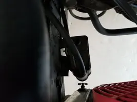

The map sensor, it won't run at all with it plugged in . Not the vacuum but the electrical plug. It runs perfect with it not plugged in.Where's that vacuum line from the front of the manifold going to?
You need to dump codes to see if the ECU is giving you a code 22 with it plugged in. Could be a bad sensor

Similar threads
- Replies
- 10
- Views
- 427
- Replies
- 10
- Views
- 272
- Replies
- 12
- Views
- 827
- Replies
- 10
- Views
- 179