
Okay “the MUCH anticipated Power Steering Pump Replacement guide” by n8rsk8r
(footnote)
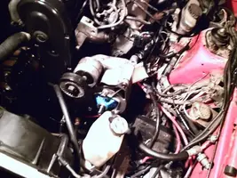
I decided to make a guide because I like to do this sort of thing, and to help others out is really cool too. I started this project thinking it was going to be a breeze. It really is a breeze if you know EXACTLY what a power steering system is supposed to act like on our vehicles. Example; I did not know that the lines can/are supposed to move side to side after install. I spent the better part of the night trying to troubleshoot why they were moving. Hell, I thought that like any other fitting, they are supposed to be tight. Not so my friend. The problem comes when the metal line moves up and down in the threaded fitting, not side-to-side. Oh man I wish I knew that going into this project. Another thing that baffled me was the O-ring issue. The instructions that come with this pump SUCK. They are REALLY uninformative. I tried to back up these with a Haynes manual. No luck there, they were just the, take the pulley off, now remove the lines, and next remove the bolts. Okay, okay that is all well and good, but nowhere does it get technical, i.e.. your lines will move once tightened, or you don’t need to do anything with all these O-rings we give you to confuse you. LOL
***WHAT YOU WILL NEED FOR THIS PROJECT***
- 15/16” combo box/open end wrench (USE: Pressure Fitting on P/S pump)
- 17mm combo box/open end wrench (USE: 2 - Alternator bolts)
- 9/16” combo box/open end wrench (USE: 1 – right hand side for P/S pump-end going to bracket)
- 18mm open end wrench (USE: the pressure line going from pump to rack, the fittings that are threaded into rack)
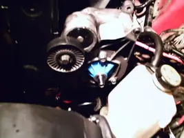
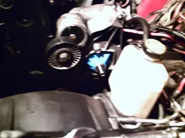
- 5/8” box end wrench (USE: Idler Pulley bolt – to release pressure so you can take the belt off/on)
- 17mm deep well socket (USE: 2 – Alternator bolts, left hand side for P/S pump-end going to bracket)
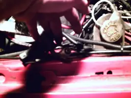
- 1/2" mid-deep socket (USE: taking off/ reinstalling P/S pump pressure line bracket to the side of Radiator overflow bottle.)
- 1 - 3/8” ratchet
- 1 - dead blow hammer
- Rags - tons o’ rags
- 2 - 32 oz bottles Power steering fluid
- 6 cans – brake cleaner
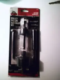
- Pulley Puller/Installer Kit
- 1 - flat head screwdriver
- 1 - P/S pump-end (minus the reservoir)
- 1 - P/S filter
- 1 - P/S pressure line
- 1 - P/S return line (non pressurized)
- 4 - small hose clamps
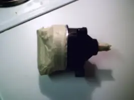
Okay here is a P/S pump-end without reservoir:


I took the time and taped the part up (first I had to clean the unit, there was A LOT of fluid all over it from shipping!) after the vital areas were covered (all areas that would be in the pump reservoir and the shaft area) I sprayed the P/S pump-end with paint-stripper. It took about half a can (in 4 coats) helping the stripper in between coats with both a wire brush and paper towels (BTW use chemical gloves while doing this, that stuff is NASTY! Oh and has chemicals that “in the state of California have been known to cause cancer” <- I guess if you don’t live in Cali, then you don’t have to worry bout it?!?!)
Here is the P/S pump-end stripped of paint:


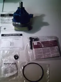
A look at the P/S pump-end and how I masked it off, this is after it is fully painting and waiting to dry:


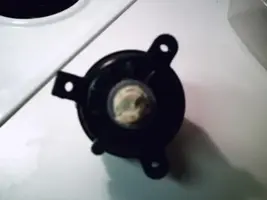
Okay I took all the extra tape off, leaving the spot where the fluid pick up is, there is still quite a bit of fluid in it from remanufacturing:


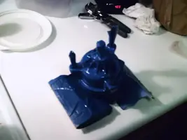
I am going to skip to when I took the old P/S pump out and separated the reservoir from the old pump-end (I will show that later on). I wanted to paint the original reservoir because that stale ass yellow color is for the birds. Here I have taped the reservoir off and am about to paint it:

View attachment 485520
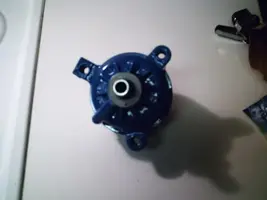
Okay here are a couple pics of my progress through the painting. I was holding on by the tape, and yep you guessed it, the tape came off making me put my fingures right into the fresh paint. Needless to say, there were a couple sand/ recoat /wet sandings done on it to pull my fingerprints outta the paint:


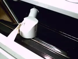
I used the oven to help dry the paint. I put it on warm, which is 170degrees F, opening the door and taped the reservoir to the door. It worked excellently!!
(footnote)
I decided to make a guide because I like to do this sort of thing, and to help others out is really cool too. I started this project thinking it was going to be a breeze. It really is a breeze if you know EXACTLY what a power steering system is supposed to act like on our vehicles. Example; I did not know that the lines can/are supposed to move side to side after install. I spent the better part of the night trying to troubleshoot why they were moving. Hell, I thought that like any other fitting, they are supposed to be tight. Not so my friend. The problem comes when the metal line moves up and down in the threaded fitting, not side-to-side. Oh man I wish I knew that going into this project. Another thing that baffled me was the O-ring issue. The instructions that come with this pump SUCK. They are REALLY uninformative. I tried to back up these with a Haynes manual. No luck there, they were just the, take the pulley off, now remove the lines, and next remove the bolts. Okay, okay that is all well and good, but nowhere does it get technical, i.e.. your lines will move once tightened, or you don’t need to do anything with all these O-rings we give you to confuse you. LOL
***WHAT YOU WILL NEED FOR THIS PROJECT***
- 15/16” combo box/open end wrench (USE: Pressure Fitting on P/S pump)
- 17mm combo box/open end wrench (USE: 2 - Alternator bolts)
- 9/16” combo box/open end wrench (USE: 1 – right hand side for P/S pump-end going to bracket)
- 18mm open end wrench (USE: the pressure line going from pump to rack, the fittings that are threaded into rack)
- 5/8” box end wrench (USE: Idler Pulley bolt – to release pressure so you can take the belt off/on)
- 17mm deep well socket (USE: 2 – Alternator bolts, left hand side for P/S pump-end going to bracket)
- 1/2" mid-deep socket (USE: taking off/ reinstalling P/S pump pressure line bracket to the side of Radiator overflow bottle.)
- 1 - 3/8” ratchet
- 1 - dead blow hammer
- Rags - tons o’ rags
- 2 - 32 oz bottles Power steering fluid
- 6 cans – brake cleaner
- Pulley Puller/Installer Kit
- 1 - flat head screwdriver
- 1 - P/S pump-end (minus the reservoir)
- 1 - P/S filter
- 1 - P/S pressure line
- 1 - P/S return line (non pressurized)
- 4 - small hose clamps
Okay here is a P/S pump-end without reservoir:
I took the time and taped the part up (first I had to clean the unit, there was A LOT of fluid all over it from shipping!) after the vital areas were covered (all areas that would be in the pump reservoir and the shaft area) I sprayed the P/S pump-end with paint-stripper. It took about half a can (in 4 coats) helping the stripper in between coats with both a wire brush and paper towels (BTW use chemical gloves while doing this, that stuff is NASTY! Oh and has chemicals that “in the state of California have been known to cause cancer” <- I guess if you don’t live in Cali, then you don’t have to worry bout it?!?!)
Here is the P/S pump-end stripped of paint:
A look at the P/S pump-end and how I masked it off, this is after it is fully painting and waiting to dry:
Okay I took all the extra tape off, leaving the spot where the fluid pick up is, there is still quite a bit of fluid in it from remanufacturing:
I am going to skip to when I took the old P/S pump out and separated the reservoir from the old pump-end (I will show that later on). I wanted to paint the original reservoir because that stale ass yellow color is for the birds. Here I have taped the reservoir off and am about to paint it:
View attachment 485520
Okay here are a couple pics of my progress through the painting. I was holding on by the tape, and yep you guessed it, the tape came off making me put my fingures right into the fresh paint. Needless to say, there were a couple sand/ recoat /wet sandings done on it to pull my fingerprints outta the paint:
I used the oven to help dry the paint. I put it on warm, which is 170degrees F, opening the door and taped the reservoir to the door. It worked excellently!!
Attachments
-
 black1.webp6.8 KB · Views: 712
 -
 black3.webp7.1 KB · Views: 839
 -
 black2.webp5.8 KB · Views: 685
 -
 raw2.webp7.9 KB · Views: 704
 -
 raw1.webp8 KB · Views: 724
 -
 raw3.webp8.2 KB · Views: 691
 -
 fullymasked2.webp11.2 KB · Views: 684
 -
 fullymasked4.webp11.3 KB · Views: 709
 -
 fullymasked1.webp12.2 KB · Views: 752
 -
 untaped3.webp7.9 KB · Views: 736
 -
 untaped2.webp8.4 KB · Views: 673
 -
 untaped1.webp7.9 KB · Views: 673
 -
 PHTO0045.webp11 KB · Views: 706
 -
 PHTO0044.webp12 KB · Views: 716
 -
 PHTO0060.webp6.3 KB · Views: 696
 -
 PHTO0049.webp13 KB · Views: 686
 -
 PHTO0047.webp11.9 KB · Views: 714
 )
)


 The filter was $17.99. That is the one they had in stock. There were actually two other choices; both had to be ordered. One of those was $12.99, and the other was $22.99. They had this one, so I took it. Precious coffee was lost during the filming of this picture
 :
:


")