
I use the Audi/VW dual temp switch. It's a 3 wire connector, you provide 12V to the switch and then at the high and low temp set points a 12V signal is sent from switch to trigger my relays.These temp switches - are they meant to be used inline on a ground or a + voltage application?
You are using an out of date browser. It may not display this or other websites correctly.
You should upgrade or use an alternative browser.
You should upgrade or use an alternative browser.
PWM Fan Control
- Thread starter Mustang5L5
- Start date

Hey Mike and nickyb, I picked up one of these modules from a 2011 Infinity G25 at the wreckers to mess around with it. So here is what I figured out tonight.No. That relay is just an on/off relay. No soft-start
I started with an OEM Contour fan setup with the factory wiring including the use of the thermoresistor for low speed basically what I talked about in my video in this thread. I do not have a PWM controller so wanted to see what would happen.
So I have a ground from the Contour harness that I connected to one of the output grounds for the module. Then I connected either the low speed power wire or the high speed wire. Then just connected main power and ground for module to a battery. Both worked as they normally do on a Contour AND BOTH HAD A SOFT START.
This means you can have an alternative dual speed Contour fan set up with soft start for both modes. Simply take your dual temp sensor (BMW, Audi/VW, whatever), ideally installed in lower rad hose or discharge side of rad. Wire the low speed output from your sensor to trigger a relay that will provide power to the thermoresistor. The second wire at the thermoresistor will then connect to the power wire for the module. Wire each of the fans to the module as you have shown Mike in your video above. Then take the high speed output from your sensor to trigger another relay that will connect to the power wire for the module. This will give you Contour high and low speed with soft starts on each.
You will be able to use lower rated relays (OEM Contour being 70A). As Mike indicated in post #1, 30A relays should suffice for providing power to the module. Wire gauge can be reduced as well.
How would the wiring diagram look like. Just like Mike's in post #1 except the "key on" would be the low or high speed signal from the temp switch. There would be 2 relays (one for high, one for low) and they would both connect to the red wire going into the module. The low speed red wire would go through the thermoresistor before connecting to the module.
Video demonstrating soft starts without PWM.
View: https://www.youtube.com/watch?v=bSmm_iDqrzc
Do you have a meter that can measure amps to see that it is soft-starting?
The reason I say that is because my fan starts up much slower. It’s a much more gradual ramp.
Try this. Take the module and hook the power/ground up directly to the battery. Ground the “pwm wire” to the same Neg terminal. Now remove the pwm wire and the fan should ramp up to full speed. Is it the same rate ij which is goes from off to full speed?
I know if I don't go through the module, both high and low speeds start much harder and at full speed faster than in the video. I don't have a meter with amp reading handy to check peak amps so that will have to wait for another day.
From what I have figured out, the PWM input is cutting power, not giving power. Just like day time running lights on cars, manufactures pulse the high beam lights to get the dimmer than low beam lighting. So not using it still allows fans to run, only at top speed.
Also, the low speed on Contour fans is determined by reducing the voltage through the thermoresistor to "burn off some energy". Reducing the input voltage going into the module will do the same, reduce fan top speed. If you want low speed to run slower, simply add resistance to "burn off more energy".
Now that I look at the video more in detail, I see how you did it. You are right it all goes through the module so it has to be soft-starting.
Any way to put together a crude wiring diagram?
Any way to put together a crude wiring diagram?
Will do. Maybe later today, if not it will be a couple days.Any way to put together a crude wiring diagram?
I don't have a copy of AutoCad at home or else I would have used that. I actually used Visio. Here it is...Microsoft Paint. Comes with Windows and is used by [all] the drafting pros.
This is what I was thinking as far as wiring a functional system in a car. You would have factory Contour high and low speeds (not variable like if using PWM) with soft start on each. I checked earlier today and low speed powering through the thermoresistor was about 8V going to the fans.
I'm waiting,sounds great to me. Thanks.Will do. Maybe later today, if not it will be a couple days.
I don't have a copy of AutoCad at home or else I would have used that. I actually used Visio. Here it is...

This is what I was thinking as far as wiring a functional system in a car. You would have factory Contour high and low speeds (not variable like if using PWM) with soft start on each. I checked earlier today and low speed powering through the thermoresistor was about 8V going to the fans.
Ah. Now it makes sense to me.
Here's an idea. That unused PWM wire? Hook that up to a relay with the other end to chassis ground. WIth the relay activated, it will connect that wire to ground which should shut the fans off. You can hook this to the WOT relay so that if you go full throttle it will shut the fans down.
Of course, that might translate to 1/2HP of reduced drag on the alt, so not sure it's worth it.
If you wanted to have a manual trigger in the diagram above, you could wire a toggle switch feeding 12V into pin 86 on either or both speeds. In my Mustang my toggles are lighted so by wiring them into pin 86, the light comes on when the relay gets triggered. This way you know when the fans are on.
Wow Mike, that's a good find! Would that controller work with MicroSquirt and a Lincoln Mark 8 fan?
The M8 fan is a single blade but dual speed.
I have had the fan laying around for almost 6 years now, never had the time to install it as I want to install my 130 AMP alternator first.
The M8 fan is a single blade but dual speed.
I have had the fan laying around for almost 6 years now, never had the time to install it as I want to install my 130 AMP alternator first.
I don't think it is needed as I would bet most of the time you are driving around the fans won't be on (if picking up temp signal at discharge side of rad or lower rad hose).You can hook this to the WOT relay so that if you go full throttle it will shut the fans down.
Of course, that might translate to 1/2HP of reduced drag on the alt, so not sure it's worth it.
IMO it just adds complexity that is not needed. Keep It Simple Sxxxx (Stupid, Silly, Smartguy, .... interchange with appropriate word)
So, I’m trying really hard to run this b210b pwm controller with my arduino uno…
From what I can tell though, the controller needs 12v+ to be modulated. I tried every frequency available with arduino, with both 3.3v and 5.0v, and the controller didn’t recognize the pwm command…. Constant full speed.
I tried a pwm module, similar to what 5L5 had in the video, on 3.3v and 5.0v…. Still the controller just went full speed.
However, 12v+ from the pwm module and now the controller the ran perfectly!
I even noticed some built in hysteresis…
21% on, but shuts back off at 18%.
Has anyone else been able to run the controller with pwm of lower/logic level voltages?
I ordered some pnp transistors, and will continue working it when they get here…
Nope, finally confirmed, the fan control module is looking for pwm+.
Which part number module are you running?
I was able to get mine to both operate on the PWM+ amazon controller and operate with my Megasquirt which is ground-switching PWM. Only difference is i had to invert the duty cycle to get it to operate with ground switching. In that case, 80-100% duty cycle was off and 0 was full speed.
I thought I posted the link, but here's where i got my inspiration from. Gent who used an Arduino Nano to control this. He has his code in post #11
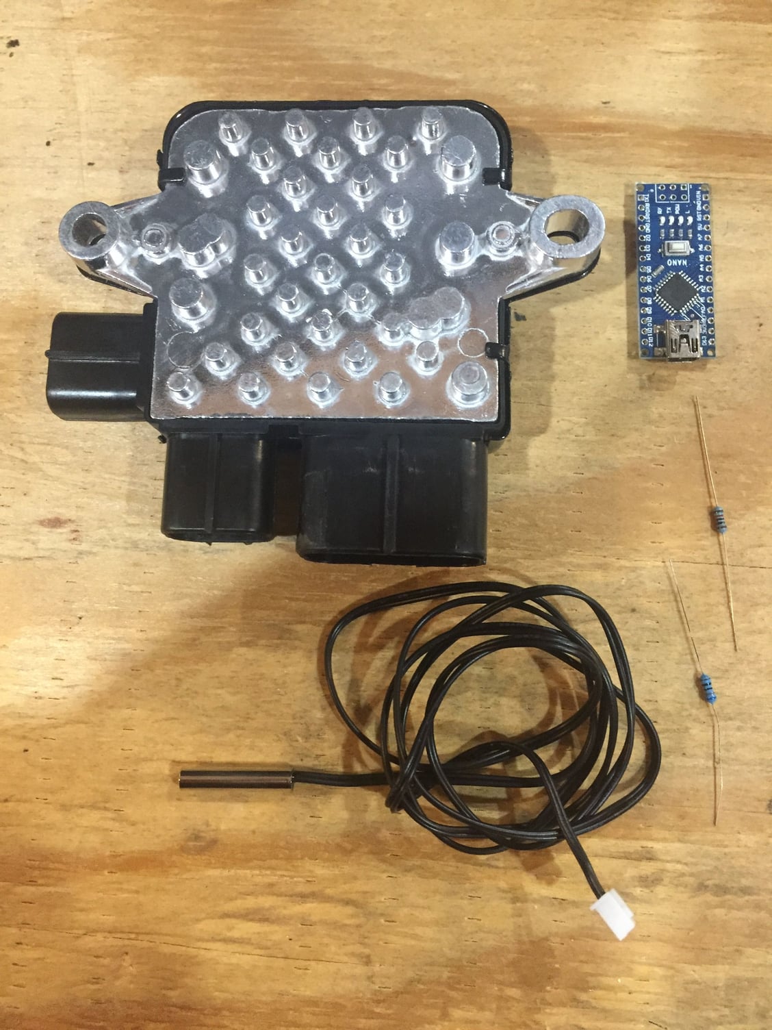
Variable Speed PWM Fan Control under $25 or less DIY - LS1TECH - Camaro and Firebird Forum Discussion
Forced Induction - Variable Speed PWM Fan Control under $25 or less DIY - This thread has gotten really big and it's pretty hard to find stuff, so I'm adding an index to key posts. Post Number) Topic. 1) Arduino controlled fan using a Mistubishi PWM fan module, Arduino Nano and a standalone NTC...
ls1tech.com
Similar threads
- Replies
- 4
- Views
- 130
- Replies
- 1
- Views
- 245
- Replies
- 9
- Views
- 2K
- Replies
- 0
- Views
- 102