Relay diagram needed

Mikie

the ahead of you horseman
Aug 2, 2000
517
1
0
Belmont NC
Hissin or any of the other electric gurus....

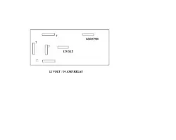
I have a 30amp 12 volt relay and really need to know what prongs are what. The numbers are not included on this unit so I have no idea.

I am including a drawing of the bottom where the prongs stick out and I have positively identified 2 of the prongs.

I am using this to wire up my e fan.

I put question marks where Im not sure. Also please dont tell me the numbers as they are still greek to me. I just need to know which one goes where in the application.

Thanks bunches guys!


Mike
 
here is the diagram
 

Attachments

  • RELAY.webp
    RELAY.webp
    4.6 KB · Views: 139
This is as good a method as any. Since it is a 30 amp circuit, I would run a 10 gauge wire and fuse the power wire coming from the starter solenoid. The red wire on the low coolant sensor or the red/green wire on the ignition coil are good sources of low current power for a relay coil.

attachment.php


Important: note that one end of the diode case has a band around it. The band goes towards the powered side of the circuit. The other end goes to ground. If you reverse the diode, you will make smoke.

Note that Radio Shack has a suitable relay & socket if you don't want the red fan off LED.

Relay Radio Shack Catalog #: 275-226
Relay socket Catalog #: 55017871
 
Thanks a bunch guys.

Tmoss,
the relay came out of a kit for door lock actuators that I didnt need at the time. It says 12volt, 30amp, spdt on the side, but bottom it has none of the standard numbers you mention. It has a 1 , 2, 1m , 2m, and a + symbol beside one of the poles.

Thanks
Mike
 
then the numbers on the diagrams we gave you won't work. Look at the relay diagrams though and you can use a ohmmeter to check out which post is what on yours. Two will be the pickup coil and three (one will be common to two contacts) will be the single pole contacts, which one is closed when off and the other is open - then they swap when the coil is picked up. The contacts will have very low resistance (less than one ohm) and the coil will have more but not ifinity (open ciurcuit)
 
Ok,
Well to save myself some grief, I just ran by the auto parts store...well actually 3 different ones to find a bosch 30 amp relay with the numbers you mentioned on them. Side note! Im really worried about the kids they are hiring in these stores nowadays as advance and autozone both guys didnt know what a relay was. They kept asking for my vehicle info and couldnt understand that , that relay is not already on the car. I about pulled my freakin hair out. To my suprise a little ole lady at pep boys walked over to isle 3 and picked it from the shelf for me. I said "bless your heart " and carried on my merry way.

I will use the diagram and also picked up my 10 g wire while there. I know I have to go 10 g from the fans to the relay , but can I go 12 g from the relay to the other points for hookup? Running 10g all the way to the fuse box inside for the acc switch would be a challenge. They only gave me 8ft on the entire roll of wire.

Thanks again.
 
Though I was mentioned, I didnt post before because you have the real gurus all posting here already. :nice:

With your newest post, I'll reply (I'm not familiar with the nomenclature on that other relay you have. When I use 451M's, I dont think they have nomenclature like that, so I'm more useless than normal).

Honestly, the best (most tractable route) is the Bosch 75 amp relay. It uses screw-on connections as I recall.

For your relay, Jrichker and Tom have you covered. :nice: Based on some of the PM's I get, the diagrams are confusing to some folks. Fi so:

Remember, for the coil wires (85 and 86) you can use 18 AWG. On the common and N.O. (30 and 87, respectively), you use the 10 AWG.

You'll have fused battery power going to 30. 10 AWG.
You'll have 10 AWG going from the fan + terminal to 87.
You'll have 85 receiving ground.
You'll have 86 receiving 12 volts.

Of 85 or 86, one or the other will be interrupted with a manual or automatic (or both) switching device (so the fan runs at appropriate times).

Good luck.
 
You will need 10 gauge wire for all the wire that supplies power or ground to the fan itself. There is 30 amps all along those wires, so they need to be big enough to do the job.

You can use 18 gauge wire for the relay coil (contacts #85 & 86 on the relay case)
 
Update for all that is interested in my progress.

I have an 02 GT electric fan that I wanted to incorporate into my 93 Lx and ditch the rotating mass on the water pump pulley that was cracked and delapodated to begin with.
Some said it Might fit, while others were really sketchy on it all together.
It fit in and works perfectly. Now you have to make your fittaments with zip ties instead of the factory bolts on the radiator, but it worked great!
It looks as factory as anything else on the car.

As for the wiring,
I took the advice above, but only connected one relay and basically ran it to the switched side of the ignition. In a nutshell, when you crank the car or flip to battery the fan will spin in slow setpoint. I didnt go with a thermal switch yet, but may incorporate that later on.

The car still runs at the same temps it did with the old fan ( in the slow position in 97 degree heated stop and go traffic).

Ultimately I am super satisfied with this mod and noticed a seat of the pants increase after finishing. The car will not keep traction in 1st and second gears now...at all.

Again,
Thanks t oTmoss, Jrichker and Hissin5.0
Very valuable members here on SN.

:nice:
 
I used my dremel to pop holes in the bottom tabs on the bottle. Then I ran zip ties from the bottom of the fan (small holes there also) looped through and zipped the bottom nicely. In the middle there already was a push pin hole in the bottle, so I dremeled out a small hole in the corner of the fan housing and zipped it. Look closely at the top of the reservoir bottle in that pic and see if you can notice the wire loom running from the radiator to the bottle?
That is a zip tie threaded through the radiator and looped through the top push pin hole of the reservoir. I put on the loom to clean it up a bit.

I am anal retentive about stuff looking clean and cant stand wire dangling and hanging...lol

I made all of my electrical connections with butt connectors and coated them with solder and shrink wrapped them.
 
I agree - that looks real nice. :nice: Those fans aren't slim are they? Sheesh.

When you get Tom's seal of approval, ya done good. :D