Going to piggy back on this thread as I just finished the MRM Mk3 relocation kit. Have had the kit for a while and figured while I had the car down for a lot of maintenance and installing stuff I have had for years it would get installed as well. I ended up installing it between the core support and the cold air kit pipe where it goes through the inner fender. Made an aluminum bracket to mount the heat sink on and bolted that to the bottom of the front inner fender.

Ended up getting different mounting hardware but used the aluminum spacers provided. Drilled the spacers out to accommodate the 1/4-20 x 2-1/2" stainless steel machine screws with nylock nuts.

Bracket to car mounting hardware are stainless steel hex cap screws with nylock nuts:

Used the hex cap screws included with the kit to mount up my existing TFI module. Used it rather than my new one because I know it works and I do not want to chase myself when I get the car back together and for some reason it does not want to run.

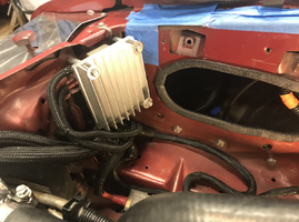
Installed:


Dummy module installed on the distributor:

Glad I was able to find the little ratcheting wrench for the TFI modules I bought about 20 years ago. Had to loosen up the distributor to get at the screws that hold the TFI on so I just used some white paint to mark the as found position of the distributor.
Ended up getting different mounting hardware but used the aluminum spacers provided. Drilled the spacers out to accommodate the 1/4-20 x 2-1/2" stainless steel machine screws with nylock nuts.
Bracket to car mounting hardware are stainless steel hex cap screws with nylock nuts:
Used the hex cap screws included with the kit to mount up my existing TFI module. Used it rather than my new one because I know it works and I do not want to chase myself when I get the car back together and for some reason it does not want to run.
Installed:
Dummy module installed on the distributor:
Glad I was able to find the little ratcheting wrench for the TFI modules I bought about 20 years ago. Had to loosen up the distributor to get at the screws that hold the TFI on so I just used some white paint to mark the as found position of the distributor.