TPS ADJ.DUMBASS MOVE

KGOFF

New Member
Nov 25, 2007
63
0
0
nj
87 GT With mass air converstion from 89gt.I was hoping to adj TPS to .98v and I get no reading at all OR COMES BACK AT OVER 300?I thought I was having computer problems and Im thinking this confirms my problem.It has been running rich(stinking up the garage),no start then it will start 20 mins later,shut her down and will not start again and no codes show when dumped but check engine light is on.I have no pollution devices at all(EGR,VACUME,CATS ALL GONE).Everything from the block up is new(fuel rails and regulator,braided fuel lines,upper and lower intake,MSD coil,plugs,module,70MM throttle body and egr spacer,headers,x-pipe,pcv and screen,water pump,oil pump and pick up,pullys,rad,180 stat,electric fan and stat,timing chain and cover,A9P computer and harness,3g alt,mini starter and all heavy guage wiring!
Here is where I become an ass!After the rebuild it ran good.I was going to dump the codes like Ive done a million times and I connected the 12v hood light to the diag.plug.Now the car has the issues I listed above.Is it what I think it is?I already purchased a new comp.and waiting for its arrival!
Thanks
 
Alright, I really tried my best to follow that, but I can't. Your TPS voltage is over 300V? That's not possible. Maybe 3.00V. Otherwise, I'm not sure what the question is?
 
If you hooked up a 12v source to the diagnostic plug, hard to tell what you messed up, but it probably wasn't good for it. Look at a wiring schematic to see where the wire goes that you put 12v to and that might help you figure out what got damaged.
 
Computer will not go into diagnostic mode on 86-90 model 5.0 Mustangs

Disconnect the battery positive terminal before making any resistance checks.
The small voltage drop in the battery cables will cause incorrect resistance readings.


Computer diagnostic connector:

B.jpg


How it is supposed to work:
The black/white wire (pin 46) is signal ground for the computer. It provides a dedicated
ground for the EGR, Baro, ACT, ECT, & TPS sensors as well as the ground to put the
computer into self test mode. If this ground is bad, none of the sensors mentioned will work
properly. That will severely affect the car's performance. You will have hard starting, low power
and drivability problems.
Since it is a dedicated ground, it passes through the computer on its
way to the computer main power ground that terminates at the battery pigtail ground. It should
read less than 1.5 ohms when measured from anyplace on the engine harness with the battery
pigtail ground as the other reference point for the ohmmeter probe.

What sometimes happens is that the test connector black/white wire gets jumpered to power.
There is a dark brown connector with a black/orange wire near the diagnostic connector. It is
the 12 volt power to the under the hood light. If this happens, it either burns up the wiring or
burns the trace off the pc board inside the computer. That trace connects pins 46 to pins 40 &
60. Only an experienced electronics technician can open the computer up & repair the trace if
it burns up and creates an open circuit.

The STI (Self Test Input ) is jumpered to ground to put the computer into test mode. The STI
has a gray connector shell and a white/red wire Jumpering it to power can produce unknown
results, including damage to the computer. The ohm test simply verifies that there are no breaks
in the wiring between the test connector and the computer input.

How to test the wiring :
With the power off, measure the resistance between the computer test ground
(black/white wire) on the self test connector and battery ground. You should see less than
1.5 ohms.

attachment.php


If that check fails, remove the passenger side kick panel and disconnect the computer
connector. There is a 10 MM bolt that holds it in place. Measure the resistance between
the black/white wire and pin 46 on the computer wiring connector: it should be less than
1.5 ohms. More that 1.5 ohms is a wiring problem. If it reads 1.5 ohms or less, then the
computer is suspect. On the computer, measure the resistance between pin 46 and pins
40 & 60: it should be less than 1.5 ohms. More that that and the computer’s internal
ground has failed, and the computer needs to be replaced.

If the first ground check was good, there are other wires to check. Measure the
resistance between the STI computer self test connector (red/white wire) and pin 48 on
the computer main connector: it should be less than 1.5 ohms. More that 1.5 ohms is a
wiring problem

The following is a view from the computer side of the computer wiring connector.
eec04.gif


Diagram courtesy of Tmoss & Stang&2birds

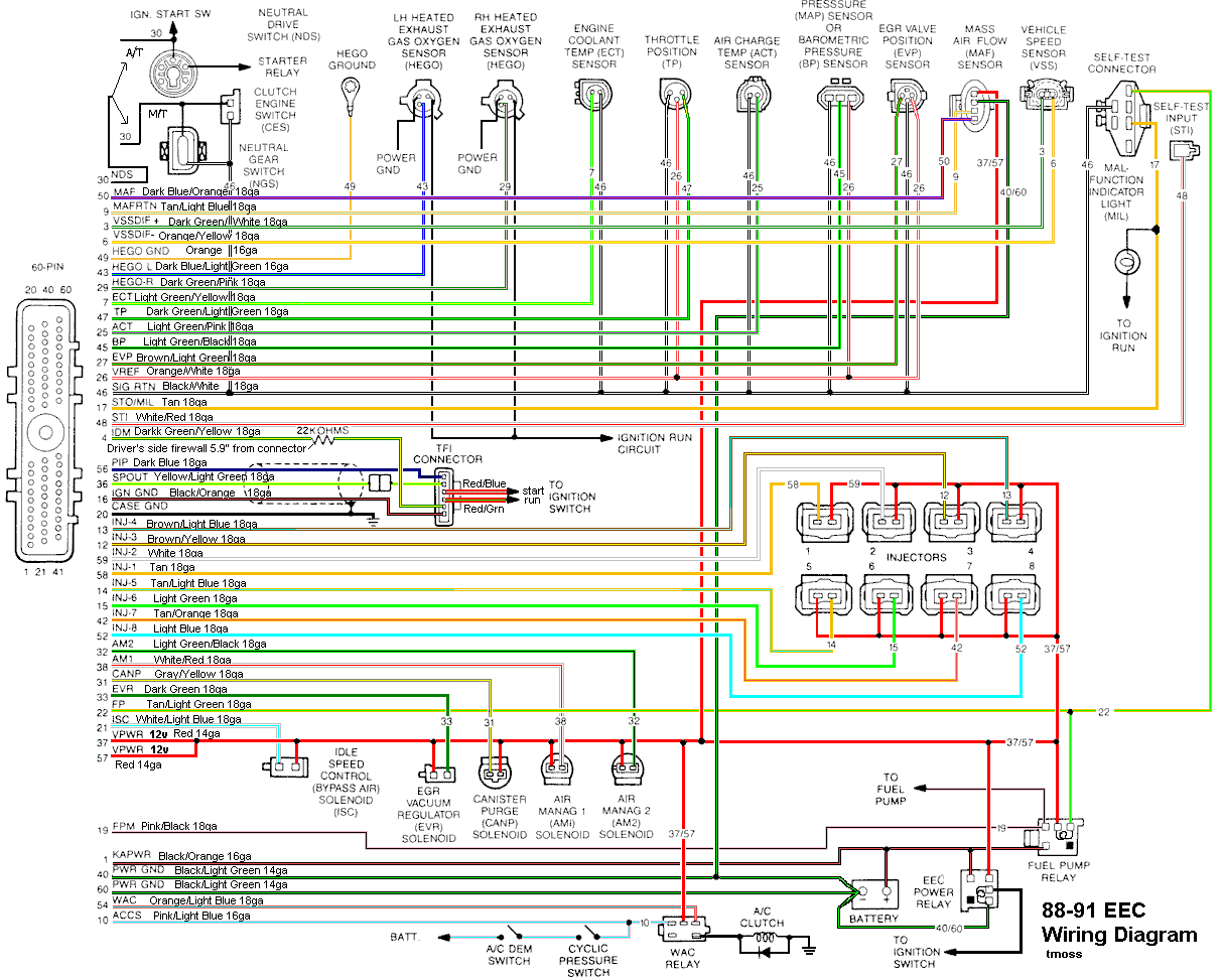
Check out the diagram and notice all the places the black/white wire goes. Almost every
sensor on the engine except the MAF is connected to it.
88-91_5.0_EEC_Wiring_Diagram.gif


See the following website for some help from Tmoss (diagram designer) & Stang&2Birds
(website host) for help on 88-95 wiring Mustang FAQ - Engine Information

harness02.gif
 
Computer will not go into diagnostic mode on 86-90 model 5.0 Mustangs

Disconnect the battery positive terminal before making any resistance checks.
The small voltage drop in the battery cables will cause incorrect resistance readings.


Computer diagnostic connector:

B.jpg


How it is supposed to work:
The black/white wire (pin 46) is signal ground for the computer. It provides a dedicated
ground for the EGR, Baro, ACT, ECT, & TPS sensors as well as the ground to put the
computer into self test mode. If this ground is bad, none of the sensors mentioned will work
properly. That will severely affect the car's performance. You will have hard starting, low power
and drivability problems.
Since it is a dedicated ground, it passes through the computer on its
way to the computer main power ground that terminates at the battery pigtail ground. It should
read less than 1.5 ohms when measured from anyplace on the engine harness with the battery
pigtail ground as the other reference point for the ohmmeter probe.

What sometimes happens is that the test connector black/white wire gets jumpered to power.
There is a dark brown connector with a black/orange wire near the diagnostic connector. It is
the 12 volt power to the under the hood light. If this happens, it either burns up the wiring or
burns the trace off the pc board inside the computer. That trace connects pins 46 to pins 40 &
60. Only an experienced electronics technician can open the computer up & repair the trace if
it burns up and creates an open circuit.

The STI (Self Test Input ) is jumpered to ground to put the computer into test mode. The STI
has a gray connector shell and a white/red wire Jumpering it to power can produce unknown
results, including damage to the computer. The ohm test simply verifies that there are no breaks
in the wiring between the test connector and the computer input.

How to test the wiring :
With the power off, measure the resistance between the computer test ground
(black/white wire) on the self test connector and battery ground. You should see less than
1.5 ohms.

attachment.php


If that check fails, remove the passenger side kick panel and disconnect the computer
connector. There is a 10 MM bolt that holds it in place. Measure the resistance between
the black/white wire and pin 46 on the computer wiring connector: it should be less than
1.5 ohms. More that 1.5 ohms is a wiring problem. If it reads 1.5 ohms or less, then the
computer is suspect. On the computer, measure the resistance between pin 46 and pins
40 & 60: it should be less than 1.5 ohms. More that that and the computer’s internal
ground has failed, and the computer needs to be replaced.

If the first ground check was good, there are other wires to check. Measure the
resistance between the STI computer self test connector (red/white wire) and pin 48 on
the computer main connector: it should be less than 1.5 ohms. More that 1.5 ohms is a
wiring problem

The following is a view from the computer side of the computer wiring connector.
eec04.gif


Diagram courtesy of Tmoss & Stang&2birds

Check out the diagram and notice all the places the black/white wire goes. Almost every
sensor on the engine except the MAF is connected to it.
88-91_5.0_EEC_Wiring_Diagram.gif


See the following website for some help from Tmoss (diagram designer) & Stang&2Birds
(website host) for help on 88-95 wiring Mustang FAQ - Engine Information

harness02.gif


so you cant use a reader with an 87 mustang?
 
Thankyou guys......The computer has seen better days after I beat it to death yesterday.I went to see a friend of mine who had his uncle over and lets say in short that he designed the electical system for the 87-93 mustang.I asked the question that never seems to get 1 answer.The a9p or a9l computer in an auto.He giggle and explained the only diffrence is a timing curve.The internet mythe of a9l not working on an auto is a joke(in his words).It has no control over the transmission whats so ever.It will work fine minus the high idle start that the a9p gives.