I was wondering if anyone could help with where my vacuum lines need to go. I’m not sure why the vacuum diagram on my hood and many other forums I’ve looked at all confuse me. Partly because the previous owners had a really complicated way they put together all the vac lines. However I had pulled them off to do some engine work and forgot how it all went together.
So attempting to follow the diagram I had finally gotten something put together. Now the car has a slightly low idle, and has a really bad hesitation when giving a slight amount of gas.
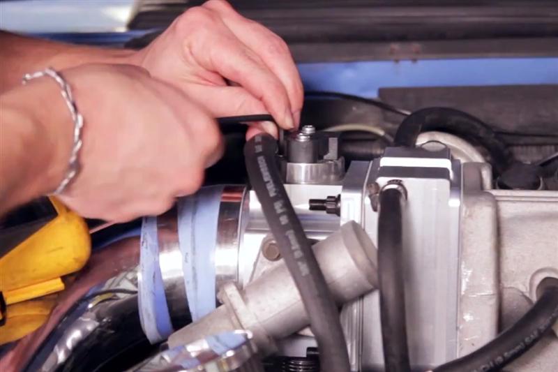
I’ve taken pictures on how I went back and tried routing things differently to hopefully solve it. Does this look right so far?
(PS: there is a trick flow upper intake on, and a different little piece that is after the throttle body which has 3 vacuum barbs.)


For context:
Green circle: is the hose coming from the canister purge valve. I can’t tell if the diagrams I’ve looked at say it goes on the throttle body vac. But some other diagrams say “man vac” which I’m guessing goes on one of the lower manifold vacuum barbs.
Yellow circle: is the hose coming from the top part of my PCV valve. It has a lower barb that had the big tube on it, then a top barb with a smaller tube (yellow circle).
blue circle: is the main vac tube on the vac tree labeled “S” and has a blue marking. Now I’ve see a photo with the blue marked tube on the large nub on the part after the throttle body, but other photos show it’s located under the upper intake manifold on the back part so I’m still sticking with that.
Red circle: is the fuel pressure regulator that is connected to the main vac line. the capped of part next to it originally had a red line for emissions stuff running to it. But I since tried swapping it to the part after the throttle body.
Now for the big PCV tube: that is running to the lower front side of the intake manifold. This is the only tube I remember that before I had taken everything apart, it was on the big nub on the part after the throttle body.
Now this is just a test, I haven’t been able to try this set up yet as it’s too late to try running the car. Is this how it’s supposed to go together? Sorry for all the confusion.
So attempting to follow the diagram I had finally gotten something put together. Now the car has a slightly low idle, and has a really bad hesitation when giving a slight amount of gas.
I’ve taken pictures on how I went back and tried routing things differently to hopefully solve it. Does this look right so far?
(PS: there is a trick flow upper intake on, and a different little piece that is after the throttle body which has 3 vacuum barbs.)
For context:
Green circle: is the hose coming from the canister purge valve. I can’t tell if the diagrams I’ve looked at say it goes on the throttle body vac. But some other diagrams say “man vac” which I’m guessing goes on one of the lower manifold vacuum barbs.
Yellow circle: is the hose coming from the top part of my PCV valve. It has a lower barb that had the big tube on it, then a top barb with a smaller tube (yellow circle).
blue circle: is the main vac tube on the vac tree labeled “S” and has a blue marking. Now I’ve see a photo with the blue marked tube on the large nub on the part after the throttle body, but other photos show it’s located under the upper intake manifold on the back part so I’m still sticking with that.
Red circle: is the fuel pressure regulator that is connected to the main vac line. the capped of part next to it originally had a red line for emissions stuff running to it. But I since tried swapping it to the part after the throttle body.
Now for the big PCV tube: that is running to the lower front side of the intake manifold. This is the only tube I remember that before I had taken everything apart, it was on the big nub on the part after the throttle body.
Now this is just a test, I haven’t been able to try this set up yet as it’s too late to try running the car. Is this how it’s supposed to go together? Sorry for all the confusion.