Cylinder balance test: use this to find dead or weak cylinders:
Revised 22-Mar-2017 Added disclaimer for the YouTube video that shows how to do a cylinder balance test.
The computer has a cylinder balance test that helps locate cylinders with low power output. You’ll need to dump the codes out of the computer and make sure that you have the A/C off, clutch depressed to the floor and the transmission in neutral. Fail to do this and you can’t do the engine running dump codes test that allows you to do the cylinder balance test.
Here's the way to dump the computer codes with only a jumper wire or paper clip and the check engine light, or test light or voltmeter. I’ve used it for years, and it works great. You watch the flashing test lamp or Check Engine Light and count the flashes.
Be sure to turn off the A/C, have the clutch depressed to the floor, and put the transmission in neutral when dumping the codes. Fail to do this and you will generate a code 67 and not be able to dump the Engine Running codes.
Here's how to dump the computer codes with only a jumper wire or paper clip and the check engine light, or test light or voltmeter. I’ve used it for years, and it works great. You watch the flashing test lamp or Check Engine Light and count the flashes.
If your car is an 86-88 stang, you'll have to use the test lamp or voltmeter method. There is no functional check engine light on the 86-88's except possibly the Cali Mass Air cars.
The STI has a gray connector shell and a white/red wire. It comes from the same bundle of wires as the self test connector.
89 through 95 cars have a working Check Engine light. Watch it instead of using a test lamp.
The STI has a gray connector shell and a white/red wire. It comes from the same bundle of wires as the self test connector.
WARNING!!! There is a single dark brown connector with a black/orange wire. It is the 12 volt power to the under the hood light. Do not jumper it to the computer test connector. If you do, you will damage the computer.
What to expect:
You should get a code 11 (two single flashes in succession). This says that the computer's internal workings are OK, and that the wiring to put the computer into diagnostic mode is good. No code 11 and you have some wiring problems.
This is crucial: the same wire that provides the ground to dump the codes provides signal ground for the TPS, EGR, ACT and Map/Baro sensors. If it fails, you will have poor performance, economy and drivability problems
Some codes have different answers if the engine is running from the answers that it has when the engine isn't running. It helps a lot to know if you had the engine running when you ran the test.
Dumping the Engine Running codes: The procedure is the same, you dump the codes and then you start the engine with the test jumper in place. Be sure the A/C is off, clutch depressed to the floor and the transmission is in neutral. You'll get an 11, then a 4 and the engine will speed up to do the EGR test. After the engine speed decreases back to idle, it will dump the engine running codes.
Trouble codes are either 2 digit or 3 digit, there are no cars that use both 2 digit codes and 3 digit codes.
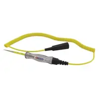
Your 86-88 5.0 won't have a working Check Engine Light, so you'll need a test light.
See AutoZone Part Number: 25886 , $10
Alternate methods:
For those who are intimidated by all the wires & connections, see
Actron® for what a typical hand scanner looks like. Normal retail price is about $30 or so at AutoZone or Wal-Mart.
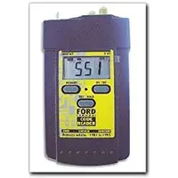
Or for a nicer scanner see
www.midwayautosupply.com/Equus-Digital-Ford-Code-Reader/dp/B000EW0KHW Equus - Digital Ford Code Reader 3145.
It has a 3 digit LCD display so that you don’t have to count flashes or beeps.. Cost is $22-$36.
Order it at Walmart for a better price and free shipping
Cylinder balance test
If you have idle or IAC/IAB problems and the engine will not idle on its own without mechanically adjusting the base idle speed above 625-750 RPM, this test will fail with random cylinders pointed out every time it runs. The IAC/IAB
must be capable of controlling the engine speed to run in the 1300-1500 RPM range. Playing with the base idle speed by adjusting it upwards will not work, the computer has to be able to control the engine speed using the IAC/IAB.
Warm the car's engine up to normal operating temperature. With the test jumper in test position, start the engine and let it stabilize. It should flash a 10 and then a 4 and maybe an 11. If no 11, then there are other codes that will be dumped.
One of the first tests it does is to open the EGR all the way, this will cause the engine to stumble and almost die. If the engine dies here then you have EGR problems.
To start the cylinder balance test, briefly floor the accelerator past 2500 RPM and let off the accelerator. The engine will stabilize at about 1300-1450 RPM and the cut off the fuel injectors one at a time. The engine speed will drop briefly and the computer will turn the fuel injector for the cylinder under test back on. Then it starts the process for the next cylinder. When it has sequenced through all 8 injectors, it will flash 9 for everything OK, or the number of the failing cylinder such as 2 for cylinder #2. Quickly pressing the throttle again up to 2500 RPM’s will cause the test to re-run with smaller qualifying figures.
Do it a third time, and if the same cylinder shows up, the cylinder is weak and isn’t putting out power like it should. See the Chilton’s Shop manual for the complete test procedure
See
View: https://www.youtube.com/watch?v=HDXrkKS4jTE
for a visual tour through the process. There is no voice narration so you have to listen carefully for the engine sounds. I posted the link for the benefit of Stangnet members who had questions about how to do a cylinder balance test. I do not own that video and I am not the creator.
Do a compression test on all the cylinders.
Take special note of any cylinder that shows up as weak in the cylinder balance test. Low compression on one of these cylinders rules out the injectors as being the most likely cause of the problem. Look at cylinders that fail the cylinder balance test but have good compression. These cylinders either have a bad injector, bad spark plug or spark plug wire. Move the wire and then the spark plug to another cylinder and run the cylinder balance test again. If it follows the moved wire or spark plug, you have found the problem. If the same cylinder fails the test again, the injector is bad. If different cylinders fail the cylinder balance test, you have ignition problems or wiring problems in the 10 pin black & white electrical connectors located by the EGR.
How to do a compression test:
Only use a compression tester with a screw in adapter for the spark plug hole. The other type leaks too much to get an accurate reading. Your local auto parts store may have a compression tester to rent/loan. If you do mechanic work on your own car on a regular basis, it would be a good tool to add to your collection.
With the engine warmed up, remove all spark plugs and prop the throttle wide open with a plastic screwdriver handle between the throttle butterfly and the throttle housing. Crank the engine until it the gage reading stops increasing. On a cold engine, it will be hard to tell what's good & what's not. Some of the recent posts have numbers ranging from 140-170 PSI. If the compression is low, squirt some oil in the cylinder and do it again – if it comes up, the rings are worn. There should be no more than 10% difference between cylinders. Use a blow down leak test (puts compressed air inside cylinders) on cylinders that have more than 10% difference.
I generally use a big screwdriver handle stuck in the TB between the butterfly and the TB to prop the throttle open. The plastic is soft enough that it won't damage anything and won't get sucked down the intake either.
A battery charger (not the trickle type) is a good thing to have if you haven't driven the car lately or if you have any doubts about the battery's health. Connect it up while you are cranking the engine and it will help keep the starter cranking at a consistent speed from the first cylinder tested to the last cylinder.
I'm fixing to dump a lot of very technical stuff on your plate, so you may want to print it out and highlight the sections that relate to your current problem.
Fuel injectors inoperative, one or more injectors either on all the time or will not squirt.
Revised 1-Jun-2014 to add computer connector pinout graphic and revise injector wiring resistance readings
Tools needed: Noid light, Multimeter (volts & ohms), 10 MM socket &
extension, & ratchet.
Note: Do all of the steps and do them in order. The results of the subsequent tests are based on the prior tests being successfully passed.
1.) Each injector has a red power wire to provide power to the injector. Turn the ignition switch to Run and remove each injector electrical connector and use the multimeter to check for 12 volts on the red wire. Each injector should have 12 volts +/- .5 volt. More voltage is always better than less voltage. No 12 volts on a singe injector and the wiring for that injector is broken inside the engine fuel injector harness.
No 12 volts on all injectors:
A.) Check for a bad connection at the 10 pin connector. Check for 12 volts at red wire on the MAF or TAD/TAB solenoids mounted on the aft side of the passenger strut tower. Good 12 volts there and you have a wiring problem with the 10 pin connectors or associated wiring.
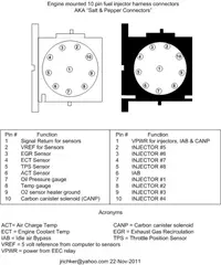
See the graphic for the location of the 10 pin connectors:
See the graphic for the 10 pin connector circuit layout.
The injector power pin is the VPWR pin in the black 10 pin connector.
B.) Bad ECC power relay. The relay is on top of the computer, it provides power to the fuel injector system. This is relevant ONLY if you do not have power to all injectors.
It is somewhat difficult to get to, since it requires you to remove the computer from its 2 bolt mounting.. If the relay or socket is bad, you will not have 12 volts on any of the red wires in the engine compartment or to pins 37/57 on the computer. The pins 37/57 are the main power feed to the computer.
C.) Blown fuse link – The blue fuse link for the computer is up near the starter solenoid. Check for no 12 volts on the ECC relay socket or computer black/orange wires. No 12 volts and the fuse link is blown open. If the fuse link blows, there is no power for any of the computer functions.
D.) Bad wiring. Broken or damaged red wire to the chassis side of the 10 pin connectors.
Some basics about the computer:
Remember that the computer does not supply power for any actuator or relay. It provides the ground necessary to complete the circuit. That means one side of the circuit will always be hot, and the other side will go to ground or below 1 volt as the computer switches on that circuit.
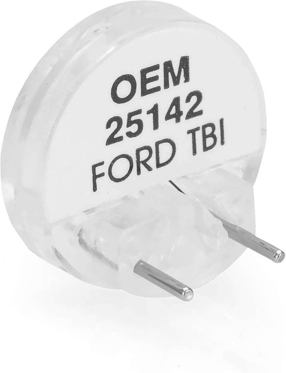
2.) Get a noid light from AutoZone or other auto parts store, or even better a set of them.
This one is from
http://www.summitracing.com/parts/oes-25142?seid=srese1&gclid=CMXk7M6dmM0CFdgOgQodGUMHWQ and costs about $6.
3.) Use the noid light to determine that the injector pulses and isn’t stuck in the on position.
It you have a set of them install all of them and compare the pulse intensity. Install the noid lights, turn the ignition switch to Run and crank the engine. A light that doesn’t pulse and stays on has a short to ground in the computer side of the circuit. That can be either a wiring fault or a failed computer.
If this is the case, remove the passenger side lick panel and disconnect the computer connector.
There is one 10 MM bolt holding it in place. Pull the connector all the way out of the computer so that you can see the computer side pins.
Use the list from the graphic below to find the fuel injector pins for the injectors that didn’t turn the noid light off.
4.) Set the multimeter to low scale Ohms and measure between the computer ground located below the computer and the suspect fuel injector pins. You should see greater than 100 K Ohms resistance. If you see less than 100K Ohms, the wiring between the injector and the computer has an internal short to ground and needs service.
Check the harness and look for damage, kinks or frayed spots.
5.) A single noid light that never turns on is either a wiring fault, or a failed computer. Either the injector has no DC power or the computer has failed and cannot switch the injector circuit to ground. Determine if the injector has power by using the multimeter to check for 12 volts on the red wire on the suspect injector connector. No 12 volts and you have a wiring fault.
Check the harness and look for damage, kinks or frayed spots. Check the 10 pin salt & pepper shaker connectors for bent pins, corrosion and damage.
If none of the noid lights flash and you have 12 volts at each injector, check to see that you have good spark. Before you even think about replacing the computer, see step 6.
Next check the fuel injector wiring end to end. Each fuel injector has a red wire (power) and an non-read wire (computer controlled ground). Set the multimeter to low ohms and measure each non red fuel injector wire from
the fuel injector connector to the matching pin on the computer connector. You should see less than 1 Ohm. More than that means a bad connection or bad wiring.
6.) Use an ohmmeter set on the low resistance scale and measure the resistance of each injector across the two contacts inside the electrical connector. You should see between 11-16 ohms. More or less than that is a bad injector. Next measure between either one of the contacts and the metal on the injector body. You should see greater than 100,000 ohms. Don’t hold the metal probe tips with your bare hands when you make this measurement. It will give incorrect results if you do.
Once you have determined that the suspect injectors have good power and good wiring, the computer is the likely suspect, since a ground is required to complete a circuit and make it function. The computer provides the ground: if doesn’t, then the noid light will not flash. If the noid light stays on, the computer has an internal failure.
7) If you have gotten this far, then the problem is likely ignition related. Remember the noid test using all of the noid lights? All of them were supposed to be equally bright. Since you have already tested all the electrical side of the fuel injector circuit, the one remaining common item is the pip sensor inside the distributor. A failing pip sensor, damaged shutter wheel or bent distributor shaft could all cause the pulse delivered to the injectors to be faulty. A bad pip sensor will cause all the injectors not to fire and you will have no spark. Dumping the codes will usually show a code 14.
8) Spark plugs indicate one or more cylinders not firing: use the multimeter to measure the resistance of the spark plug wires. The wires should measure 2000 ohms per foot of length. A 2 foot wire would be 4000 ohms and a 3 foot wire would be 6000 ohms. Some Taylor and Accel wires have metal cores and will measure much less: that’s OK.
Next examine the spark plug wires very carefully for burn spots, cracks and damaged insulation. One good thing to try is to start the engine while the car is a very dark area, open the hood and look for sparks or blue glow. They indicate the electricity is leaking out of the spark plug wires.
Thanks to Tmoss & Stang&2birds at
www.veryuseful.com/mustang/tech/engine/ for some of the graphics
Thanks also to
www.oldfuelinjection.com for some of the graphics.