no spark

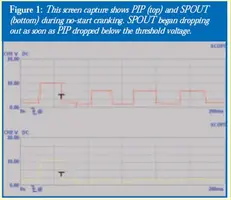
Spark with the SPOUT out, but not with the SPOUT in suggests a PIP problem. The PIP signal level needs to be above 6.5 volts to trigger the computer, but only needs to be 5.75 volts to trigger the TFI module. Hence with a weak PIP signal, you could get spark but no injector pulse.

See http://www.wellsmfgcorp.com/pdf/counterp_v8_i2_2004.pdf and http://www.wellsmfgcorp.com/pdf/counterp_v8_i3_2004.pdf for verification of this little detail from Wells, a manufacturer of TFI modules and ignition system products.
 
You have an issue with VPWR reaching the injectors. Each injector should see continuous 12V when the key is on. Before you replace anything, find the source of the wiring issues. Also, because of the lack of power, any noid light testing you did is invalid. Once you restore 12V to the injectors, recheck injector pulse with a noid light.

this would be the red wire(361) from relays? he says he did somethimg to fuel pumps but hasnt stated what


which is 37/57 in link

Complete computer, actuator & sensor wiring diagram for 88-91 Mass Air Mustangs
http://www.veryuseful.com/mustang/te...ng_Diagram.gif
 
okay i will check the pip voltage. as far as the questions about the fuel pump it will not cut on with the ignition it has power everywhere it is suppose to but stops at the relay. i put 5 different relays on it and still power goes to relay but not out. so right now i have it wired on a toggle to just try and get the engine to start.
 
okay i will check the pip voltage. as far as the questions about the fuel pump it will not cut on with the ignition it has power everywhere it is suppose to but stops at the relay. i put 5 different relays on it and still power goes to relay but not out. so right now i have it wired on a toggle to just try and get the engine to start.

Unless you have an oscilloscope or Graphing Digital Multimeter, you will not be able to accurately measure the PIP output voltage. It is a slow repetition rate square wave, not a constant DC voltage.

The picture below was taken from the Wells article. It shows what the PIP output voltage looks like on a Graphing Digital Mutlimeter.

attachment.php


Two clues for a PIP with low output:
1.) Is that you get spark but no injector pulse. There is no injector pulse even though the required 12 volts is present on the injector red wire. That's the reason for using the noid light to test the injectors for pulse.
2.) Clue #1 must be true in order for Clue #2 to be true: the car will often start with the SPOUT out but not with the SPOUT in.


The simplest solution is to replace the PIP sensor or the distributor.

The PIP is a Hall Effect magnetic sensor that triggers the TFI and injectors. There is a shutter wheel alternately covers and uncovers a fixed magnet as it rotates. The change in the magnetic field triggers the sensor. A failing PIP sensor will often set code 14 in the computer. They are often heat sensitive, increasing the failure rate as the temperature increases.

The PIP sensor is mounted in the bottom of the distributor under the shutter wheel. In stock Ford distributors, you have to press the gear off the distributor shaft to get access to it to replace it. Then you drive out the roll pin that secures the gear to the shaft. When you go to press the gear back on it has to lined up perfectly with the hole in the gear and shaft. I have been told that the hole for the pin is offset slightly from center and may require some extra examination to get it lined up correctly.

Most guys just end up replacing the distributor with a reman unit for about $75 exchange
 

Attachments

  • PIP output voltage.webp
    PIP output voltage.webp
    18.3 KB · Views: 166
Some new parts will arrive DOA. Don't be suprized if your replacement distributor is one of them...

Fix the no 12 volts at the red injector wires and then use the noid light to check for injector pulse.

Diagram courtesy of Tmoss & Stang&2birds
fuel-alt-links-ign-ac.gif


See the following website for some help from Tmoss (diagram designer) & Stang&2Birds (website host) for help on 88-95 wiring Mustang FAQ - Engine Information Everyone should bookmark this site.


Ignition switch wiring
http://www.veryuseful.com/mustang/tech/engine/images/IgnitionSwitchWiring.gif

Fuel, alternator, A/C and ignition wiring
http://www.veryuseful.com/mustang/tech/engine/images/fuel-alt-links-ign-ac.gif

Complete computer, actuator & sensor wiring diagram for 88-91 Mass Air Mustangs
http://www.veryuseful.com/mustang/tech/engine/images/88-91_5.0_EEC_Wiring_Diagram.gif

Complete computer, actuator & sensor wiring diagram for 91-93 Mass Air Mustangs
http://www.veryuseful.com/mustang/tech/engine/images/91-93_5.0_EEC_Wiring_Diagram.gif

Complete computer, actuator & sensor wiring diagram for94-95 Mass Air Mustangs
http://www.veryuseful.com/mustang/tech/engine/images/94-95_5.0_EEC_Wiring_Diagram.gif

Vacuum diagram 89-93 Mustangs
http://www.veryuseful.com/mustang/tech/engine/images/mustangFoxFordVacuumDiagram.jpg

HVAC vacuum diagram
http://www.veryuseful.com/mustang/tech/engine/images/Mustang_AC_heat_vacuum_controls.gif

TFI module differences & pinout
http://www.veryuseful.com/mustang/tech/engine/images/TFI_5.0_comparison.gif

Fuse box layout
http://www.veryuseful.com/mustang/tech/engine/images/MustangFuseBox.gif
 
I have bought a bad distributor before and it took me weeks to finally decide to take it back and try another one because I trusted it because it was "new". Don't be like me.

My neighbor just sent a brand new "bullet" distributor (or something like that) back because it was bad brand new out of the box.

That little module in the dizzy is what causes a no spark situation, or a partial spark situation 90% of the time. I've run into it on all 3 5.0's I've owned and just got done changing the dizzy on my 93 a few months ago because it was stumbling.
 
okay replaced the computer relay and now i have 12 volts on injector wires. If i spray starter fluid in the intake the car fires up fine for few seconds. i checked the little fuel line valve and if you press it in fuel squirts out. i put a tire guage on it though and it doesn't move at all. so what should i look at next? thanks for all your help guys it was awesome to hear this thing run even if it was just for a few seconds.
 
Check injector pulsing and fuel pressure. Some parts stores loan out FP testers I guess. It's a good tool to have in your toolbox nonetheless.
 
okay i have 40 psi for fuel pressure. i bought noid light kit but the ford one that it comes with doesn't fit so i used the gm one and it does nothing. so what should i do now?

Assuming that you had the ignition switch in the Run/Start postion and had 12 volts on the injector wires, it is time to think. Or go back and look at the first checklist I posted in this thread. The information in the checklist is there so you can troubleshoot the problem in an orderly manner.

1. What does no pulse from the injectors tell you? The computer isn't seeing a trigger signal to fire the injectors or you don't have power to pins 37 & 57 on the computer.

2. You have no spark. What triggers the TFI to tell it that it is time to act as a switch and turn on the ground for the coil? Remember that an automotive circuit always needs a ground to provide a return path for the power to get back to the battery and alternator. You have voltage at the TFI and at the coil. You have a ground because the TFI is bolted to the distributor and the distributor is mounted in the engine and the engine is mounted in the car.

3. If you indeed have power to the computer pins 37 & 57, what component tells the computer it is time to fire the injectors and the coil? Think about that and you will have your answer.
 
okay i will go through the checklist again for the injectors. but yes i do have 12 volts to the injectors. so me using the none ford noid light was okay then?

Start at the top of the checklist and work your way down. That way you will find the problem. Just because a part is new does not mean that it can't be DOA and not work.

The only possible problem with the GM noid light is that it may be polarity sensitive and not work. If it doesn't fit only one way in the inector harness socket, try plugging it in the other way and testing it again.
 
ya the ford noid light little probes are to far apart to fit in the injector plug. okay for step 5 G if i get more then 3.7 volts at the tps does that mean i need to replace the tps?

TPS Troubleshooting:

The TPS sensor is a variable resistor like the volume control on most cheap radios. We have all heard them make scratchy noises as you turn them up or down. The carbon element can wear and cause a drop out spot in the output voltage. This confuses the computer because it expects to see a steady TPS voltage increase as the Throttle opens up.

Wire colors & functions:
Orange/white = 5 volt VREF from the computer
Dark Green/lt green = TPS output to computer
Black/white = Signal ground from computer

TPS troubleshooting steps:
1.) Use the Orange/white & Black white wires to verify the TPS has the correct 5 volts source from the computer.
Use the Dark Green/lt green & Black/white wires to set the TPS base voltage. Setting the TPS: you'll need a good Digital Voltmeter (DVM) to do the job. Set the TPS voltage at .5- 1.1 range. Because of the variables involved with the tolerances of both computer and DVM, I would shoot for somewhere between .6 and 1.0 volts. Unless you have a Fluke or other high grade DVM, the second digit past the decimal point on cheap DVM’s is probably fantasy. Since the computer zeros out the TPS voltage every time it powers up, playing with the settings isn't an effective aid to performance or drivability. The main purpose of checking the TPS is to make sure it isn't way out of range and causing problems.
2.) Use an analog voltmeter to check the voltage on the Dark Green/lt green & Black/white wires to make sure that it increases smoothly and doesn’t drop out or increase suddenly.

Some basic checks you can make to be sure that the sensor is getting power & ground:
Note that all resistance tests must be done with power off. Measuring resistance with a circuit powered on will give false readings and possibly damage the meter.
Check the resistance between the black/white wire on the MAP/BARO sensor and then the black/white wire on the EGR and the same wire on the TPS. It should be less than 1 ohm. Next check the resistance between the black/white wire and the negative battery cable. It should be less than 1.5 ohm.

The following power on check requires you to turn the ignition switch to the Run position.
Use a DVM to check for 5 volts on the orange/white wire. If it is missing, look for +5 volts at the orange/white wire on the TPS or EGR sensors. Use the black/white wire for the ground for the DVM.
 
If you have 12 volts at the computer, do you have VREF (4.5-5.5 volts) on the orange/white wire on the MAP/BARO sensor on the firewall? If not the computer is suspect.

If you have VREF (4.5-5.5 volts) at the MAP/BARO sensor on the firewall, do you have VREF at the EGR sensor? If not clean the 10 pin connectors and check the wiring harness.

See the graphic for the 10 pin connector circuit layout. Pin #2 on the white connector is VREF
harness02.gif