
Hello all! I was driving the car the other day and it started idle surging on me at every stop then die out of nowhere. I had just changed the clutch neutral safety sensor before I drove it the next day but am doubting it could be the reason. I thought it may have been idle air control so changed that, the ect sensor, checked the tps signal and its fine, checked the fuel pressure and it's correct. I pulled off the egr and cleaned that. Changed the plugs and even installed a new coil. It will start then die every time. Everything I did changed nothing. I pulled the vacuum line off and blew smoke in the intake and smoke is coming out of the egr diaphragm like crazy, is that normal? I checked for other leaks and nothing. Will have to run codes again tomorrow but does anybody have any ideas? Car ran and started fine all winter while in storage then bam. Thanks in advance! Codes I did receive just said it was running rich, plugs we're fouled.
You are using an out of date browser. It may not display this or other websites correctly.
You should upgrade or use an alternative browser.
You should upgrade or use an alternative browser.
Engine 88 won't idle at all
- Thread starter Jays88gt
- Start date
There is a surging idle checklist in the tech forums that should get you running right, I'll link it for ya.
http://forums.stangnet.com/showthread.php?t=698148
read through it and get familiar then do the steps one by one, don't skip around, the next step depends on the one before.
http://forums.stangnet.com/showthread.php?t=698148
read through it and get familiar then do the steps one by one, don't skip around, the next step depends on the one before.
There is a surging idle checklist in the tech forums that should get you running right, I'll link it for ya.
http://forums.stangnet.com/showthread.php?t=698148There is a surging idle checklist in the tech forums that should get you running right, I'll link it for ya.
http://forums.stangnet.com/showthread.php?t=698148
read through it and get familiar then do the steps one by one, don't skip around, the next step depends on the one before.
read through it and get familiar then do the steps one by one, don't skip around, the next step depends on the one before.
Thank you! I'll go through it today. Do you know if the air (smoke) coming out of the egr is normal?There is a surging idle checklist in the tech forums that should get you running right, I'll link it for ya.
http://forums.stangnet.com/showthread.php?t=698148
read through it and get familiar then do the steps one by one, don't skip around, the next step depends on the one before.
No on the smoke. If you push the EGR plunger in and put your finger over the vac port, the Plunger should stay in until you open the vac port

Attached to the intake smoke will come out with little pressure, when I took it off I pressure tested it and it'll hold. WeirdNo on the smoke. If you push the EGR plunger in and put your finger over the vac port, the Plunger should stay in until you open the vac port
Have you performed the base idle reset procedure after changing the IAC? You need to set the idle stop screw with the IAC disconnected, and then reset the ECU.
I did do the base idle air reset after going everything and setting the tps sensor at .98. went through the idle surge list and came up with these codes engine running 23, 92, 42 and 13. It's showing the tps acting up but it's new and getting 12 volts. Cylinder test shows 7, changed spark plugs wires and still 7. I will do a compression test this weekend. What's the chances the fuel injector is wide open dumping to much fuel making it run rich?
I did do the base idle air reset after going everything and setting the tps sensor at .98. went through the idle surge list and came up with these codes engine running 23, 92, 42 and 13. It's showing the tps acting up but it's new and getting 12 volts. Cylinder test shows 7, changed spark plugs wires and still 7. I will do a compression test this weekend. What's the chances the fuel injector is wide open dumping to much fuel making it run rich?
Fix the codes and then chase the rest of the rabbits...
Code 13 & 415 - Key on Engine off - ISC did not respond properly (extends to touch throttle then retracts for KOEO) – ISC
Key on Engine running - Idle Speed Control motor or Air Bypass not controlling idle properly (generally idle too high)
If your idle is above 725 RPM, the computer will set this code. Normal idle speed is 650-725 RPM. Higher than that means that someone has mechanically set the idle speed by use of the idle speed screw, and has effectively disabled to computer’s ability to control idle speed.
Code 23 - Throttle sensor out of range or throttle set too high - TPS needs to be reset to below 1.2 volts at idle. Keep in mind that when you turn the idle screw to set the idle speed, you change the TPS setting. [/b]
You'll need a Digital Voltmeter (DVM) to do the job.
Wire colors & functions:
Orange/white = 5 volt VREF from the computer
Dark Green/lt green = TPS output to computer
Black/white = Signal ground from computer
Always use the Dark Green/lt green & Black/white wires to set the TPS base voltage.
Do the test with the ignition switch in the Run position without the engine running.
Use the Orange/white & Black white wires to verify the TPS has the correct 5 volts source from the computer.
When you installed the sensor make sure you place it on the peg right and then tighten it down properly. Loosen the back screw a tiny bit so the sensor can pivot and loosen the front screw enough so you can move it just a little in very small increments. I wouldn’t try to adjust it using marks. Set it at .6.v-.9 v.
1. Always adjust the TPS and Idle with the engine at operating temp. Dive it around for a bit if you can and get it nice and warm.
2. When you probe the leads of the TPS, do not use an engine ground, put the ground probe into the lead of the TPS. You should be connecting both meter probes to the TPS and not one to the TPS and the other to ground.
If setting the TPS doesn’t fix the problem, then you may have wiring problems.
With the power off, measure the resistance between the black/white wire and battery ground. You should see less than 2 ohms. Check the same black /white wire on the TPS and MAP/Baro sensor. More than 1 ohm there and the wire is probably broken in the harness between the engine and the computer. The 10 pin connectors pass the black/white wire back to the computer, and can cause problems.
See the following website for some help from Tmoss (diagram designer) & Stang&2Birds (website host)
http://www.veryuseful.com/mustang/tech/engine/images/88-91eecPinout.gif
See the graphic for the 10 pin connector circuit layout.
If you got 12 volts on the TPS test either your voltmeter is on the wrong range or you have some serious computer or wiring problems
Troubleshooting low or missing 5 volt Vref
All tests done with the ignition switch in the Run position but the engine is not running.
The orange/white wire supplies 5 volts reference (Vref) for the TPS, MAP/Baro and EGR sensors.
Engine Mounted sensors
The TPS and EGR get their 5 volt Vref through the engine mounted fuel injector harness & the 10 pin connectors.
See the graphic for the 10 pin connector circuit layout.
A bad connection or broken wire in the engine mounted fuel injection harness is not uncommon. Check the EGR sensor orange/white wire for good 5 volt Vref. If it is good there, the TPS has either a broken wire or bad connection.
Good 5 volt Vref at the ERG sensor, then you have a 10 pin salt & pepper connecter problem or a computer problem.
Check for 5 volt Vref on the orange/white wire at the firewall mounted MAP/Baro sensor. Good 5 volt Vref there, then the problem is in the 10 pin salt & pepper connectors or in the engine mounted fuel injection harness.
No 5 volt Vref at the MAP/Baro sensor, then the problem is either a broken wire in the main fuel injector harness or the computer has died.
Remove the passenger side kick panel to gain access to the computer.
Locate the orange/white wire (pin 26) on the computer connector and check for 5 volt Vref. Good 5 volt Vref and the computer is OK.
Diagrams courtesy of Tmoss & Stang&2birds
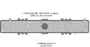
Complete computer, actuator & sensor wiring diagram for 91-93 Mass Air Mustangs
Complete computer, actuator & sensor wiring diagram for 88-90 Mass Air Mustangs
No 5 volt Vref, then the computer has died. It is time to get out your wallet and go hunting…
Expect to pay $100 or more for a replacement computer. eBay has a repair service that is less expensive.
Code 42 & 92 & 137 & 173 (engine running) System rich - Fuel control or (memory) System was rich for 15 seconds or more (no HO2S switching) - Fuel control. Look for leaking injectors, fuel pressure too high, cylinder(s) not firing due to bad ignition.
Code 42 passenger side sensor, as viewed from the driver's seat
Code 92 is the driver side sensor, as viewed from the driver's seat..
The following is a Quote from Charles O. Probst, Ford fuel Injection & Electronic Engine control:
"When the mixture is lean, the exhaust gas has oxygen, about the same amount as the ambient air. So the sensor will generate less than 400 Millivolts. Remember lean = less voltage.
When the mixture is rich, there's less oxygen in the exhaust than in the ambient air , so voltage is generated between the two sides of the tip. The voltage is greater than 600 millivolts. Remember rich = more voltage.
Here's a tip: the newer the sensor, the more the voltage changes, swinging from as low as 0.1 volt to as much as 0.9 volt. As an oxygen sensor ages, the voltage changes get smaller and slower - the voltage change lags behind the change in exhaust gas oxygen.
Because the oxygen sensor generates its own voltage, never apply voltage and never measure resistance of the sensor circuit. To measure voltage signals, use an analog voltmeter with a high input impedance, at least 10 megohms. Remember, a digital voltmeter will average a changing voltage." End Quote
Testing the O2 sensors 87-93 5.0 Mustangs
Measuring the O2 sensor voltage at the computer will give you a good idea of how well they are working. You'll have to pull the passenger side kick panel off to gain access to the computer connector. Remove the plastic wiring cover to get to the back side of the wiring. Use a safety pin or paper clip to probe the connections from the rear.
Backside view of the computer wiring connector:
87-90 5.0 Mustangs:
Computer pin 43 Dark blue/Lt green – LH O2 sensor
Computer pin 29 Dark Green/Pink – RH O2 sensor
The computer pins are 29 (LH O2 with a dark green/pink wire) and 43 (RH O2 with a dark blue/pink wire). Use the ground next to the computer to ground the voltmeter. The O2 sensor voltage should switch between .2-.9 volt at idle.
91-93 5.0 Mustangs:
Computer pin 43 Red/Black – LH O2 sensor
Computer pin 29 Gray/Lt blue – RH O2 sensor
The computer pins are 29 (LH O2 with a Gray/Lt blue wire) and 43 (RH O2 with a Red/Black wire). Use the ground next to the computer to ground the voltmeter. The O2 sensor voltage should switch between .2-.9 volt at idle.
Testing the O2 sensors 94-95 5.0 Mustangs
Measuring the O2 sensor voltage at the computer will give you a good idea of how well they are working. You'll have to pull the passenger side kick panel off to gain access to the computer connector. Remove the plastic wiring cover to get to the back side of the wiring. Use a safety pin or paper clip to probe the connections from the rear. The computer pins are 29 (LH O2 with a red/black wire) and 27 (RH O2 with a gray/lt blue wire). Use pin 32 (gray/red wire) to ground the voltmeter. The O2 sensor voltage should switch between .2-.9 volt at idle.
There is a fuse link for the O2 sensor heater power. According to Ranchero50, it is in the wiring near the passenger side hood hinge. Measuring the voltages will give a clue if it has shorted to the O2 sensor signal lead. The O2 sensor voltage should switch between .2-.9 volt at idle.[/b]
Attachments
Last edited:
The idle is high because I can't go lower without it dying which is causing the tps acting up probably even knowing it's set right causing everything else. Out of 4 foxes I've never seen anything like it. Thanks for the help, time for it to go bye bye. Don't have much hair left. Lol
Have you checked for vacuum leak?
ain't nothin there that can't be fixed, take a deep breath then start with the basics, go back through the checklist
ain't nothin there that can't be fixed, take a deep breath then start with the basics, go back through the checklist
I had a similar problem with my 89 GT. The car wouldn't idle I found out that the short hose in the tank on the pump was split and was pumping the fuel back into the tank. Very little was going up to the engine.Once I fixed that we were idling again.
@Jays88gt
@General karthief Is right on target. A vacuum leak that is so big that you cannot control the idle is what you are seeing. That is probably also the reason for the code 42/92. Find and fix the vacuum leak before doing anything else.
Finding vacuum leaks
Revised 6 May 2018 to add carbon canister plumbing as a common leak area.
There is no easy way to find vacuum leaks. It is a time consuming job that requires close inspection of each and every hose and connection.
Small vacuum leaks may not show much change using a vacuum gauge. The range of "good readings" varies so much from engine to engine that it may be difficult to detect small leaks. The engine in my first Mustang pulled about 16.5" of vacuum at 650-725 RPM, which I consider rather low. It was a mass market remanufactured rebuild, so no telling what kind of camshaft it had. Average readings seem to run 16"-18" inches at idle and 18"-21" at 1000 RPM. The only sure comparison is a reading taken when your car was performing at its best through all the RPM ranges and what it is doing now. Use one of the spare ports on the vacuum tree that is mounted on the firewall near the windshield wiper motor.
Use a squirt can of motor oil to squirt around the mating surfaces of the manifold & TB. The oil will be sucked into the leaking area and the engine will change speed. Avoid using flammable substitutes for the oil such as starting fluid, propane or throttle body cleaner. Fire is an excellent hair removal agent, and no eyebrows is not cool...
After you have done the simple visual checks and the check for vacuum leak on the underside of the intake manifold, consider doing a smoke test.
Some of the guys here have built smoke machines used to find automotive vacuum leaks. They seem to work quite well and are made mostly with parts you would have laying around in your garage. Check out smoke machine vacuum leak - YouTube and see if there is one that you could build.
The vacuum line plumbing is old and brittle on many of these cars, so replacing the lines with new hose is a good plan. The common 1/8” and ¼” vacuum hose works well and isn’t expensive.
The PCV grommet and the power brake booster check valve grommet are two places that often get overlooked when checking for vacuum leaks. The rubber grommets get hard and lose their ability to seal properly. The PVC grommet is difficult to see if it is correctly seated and fitting snugly.
The hoses and connections for the evaporative emissions (carbon canister and purge valve) are other common sources of vacuum leaks. The large vacuum outlets on the bottom side of the upper intake manifold are common hiding places for deteriorated vacuum lines and caps over unused vacuum ports.
Fuel injector O rings can get old and hard. When they do, they are prone to leaking once the engine warms up. This can be difficult to troubleshoot, since it is almost impossible to get to the injectors to squirt oil into the fuel injector mounting bosses. If the plastic caps on the fuel injectors (pintle caps) are missing, the O rings will slide off the injectors and fall into the intake manifold.
Fuel injector seal kits with 2 O rings and a pintle cap (Borg-Warner P/N 274081) are available at Pep Boys auto parts. Cost is about $3-$4 per kit. The following are listed at the Borg-Warner site ( http://www.borg-warner.com ) as being resellers of Borg-Warner parts:
http://www.partsplus.com/ or http://www.autovalue.com/ or http://www.pepboys.com/ or http://www.federatedautoparts.com/
Most of the links above have store locators for find a store in your area.
Use motor oil on the O rings when you re-assemble them & everything will slide into place. The gasoline will wash away any excess oil that gets in the wrong places and it will burn up in the combustion chamber. Heat the pintle caps in boiling water to soften them to make them easier to install.
Diagram courtesy of Tmoss & Stang&2birds

Vacuum leak due to slipped lower intake manifold gasket...
Ask Nicoleb3x3 about the intake gasket that slipped out of place and caused idle and vacuum leak problems that could not be seen or found by external examination. I don't care what you spray with, you won't find the leak when it is sucking air from the lifter valley. It simply isn't possible to spray anything in there with the lower manifold bolted in place.

Determining if you have a leak due to a slipped intake gasket as shown above. This test is only good if you can get the engine to run somewhere in the 1000-1700 RPM range
If your valve cover oil filler & PVC systems are still in the original configuration, try this:
Cap or plug the hose from the intake manifold to the PVC valve with a bolt.
Cap or plug the PVC valve with a piece of hose with a plug or bolt in it.
At that point the only vent for the crankcase is the tube from the oil filler neck to the throttle body.
Disconnect the tube that runs from the oil filler neck to the throttle body. Make sure the oil filler cap is on securely. Start the engine and put your thumb over the end of the tube that comes from the oil filler cap. If you feel suction, there is a leak. Another thing to do is to extend the tubing from the filler neck so that there is enough to stick the end in a jar or cup filled with motor oil. If it sucks up the oil, you definitely have a leak at the underside of intake manifold.
This isn't necessarily the definitive test, but it is the best thing I could come up with on short notice. If there is a lot of blowby, this obviously won't be of much help.
See the picture below to see the breather tube where in connects to the throttle body. It is close to the TPS and runs over the top of the IAC.
The following are diagrams courtesy of Tmoss & Stang&2birds

See the following website for some help from Tmoss (diagram designer) & Stang&2Birds (website host) for help on 88-95 wiring http://www.veryuseful.com/mustang/tech/engine/ Everyone should bookmark this site.
Ignition switch wiring
http://www.veryuseful.com/mustang/tech/engine/images/IgnitionSwitchWiring.gif
Fuel, alternator, A/C and ignition wiring
http://www.veryuseful.com/mustang/tech/engine/images/fuel-alt-links-ign-ac.gif
Complete computer, actuator & sensor wiring diagram for 88-91 Mass Air Mustangs
http://www.veryuseful.com/mustang/tech/engine/images/88-91_5.0_EEC_Wiring_Diagram.gif
Vacuum diagram 89-93 Mustangs
http://www.veryuseful.com/mustang/tech/engine/images/mustangFoxFordVacuumDiagram.jpg
HVAC vacuum diagram
http://www.veryuseful.com/mustang/tech/engine/images/Mustang_AC_heat_vacuum_controls.gif
TFI module differences & pinout
http://www.veryuseful.com/mustang/tech/engine/images/TFI_5.0_comparison.gif
Fuse box layout
http://www.veryuseful.com/mustang/tech/engine/images/MustangFuseBox.gif
@General karthief Is right on target. A vacuum leak that is so big that you cannot control the idle is what you are seeing. That is probably also the reason for the code 42/92. Find and fix the vacuum leak before doing anything else.
Finding vacuum leaks
Revised 6 May 2018 to add carbon canister plumbing as a common leak area.
There is no easy way to find vacuum leaks. It is a time consuming job that requires close inspection of each and every hose and connection.
Small vacuum leaks may not show much change using a vacuum gauge. The range of "good readings" varies so much from engine to engine that it may be difficult to detect small leaks. The engine in my first Mustang pulled about 16.5" of vacuum at 650-725 RPM, which I consider rather low. It was a mass market remanufactured rebuild, so no telling what kind of camshaft it had. Average readings seem to run 16"-18" inches at idle and 18"-21" at 1000 RPM. The only sure comparison is a reading taken when your car was performing at its best through all the RPM ranges and what it is doing now. Use one of the spare ports on the vacuum tree that is mounted on the firewall near the windshield wiper motor.
Use a squirt can of motor oil to squirt around the mating surfaces of the manifold & TB. The oil will be sucked into the leaking area and the engine will change speed. Avoid using flammable substitutes for the oil such as starting fluid, propane or throttle body cleaner. Fire is an excellent hair removal agent, and no eyebrows is not cool...
After you have done the simple visual checks and the check for vacuum leak on the underside of the intake manifold, consider doing a smoke test.
Some of the guys here have built smoke machines used to find automotive vacuum leaks. They seem to work quite well and are made mostly with parts you would have laying around in your garage. Check out smoke machine vacuum leak - YouTube and see if there is one that you could build.
The vacuum line plumbing is old and brittle on many of these cars, so replacing the lines with new hose is a good plan. The common 1/8” and ¼” vacuum hose works well and isn’t expensive.
The PCV grommet and the power brake booster check valve grommet are two places that often get overlooked when checking for vacuum leaks. The rubber grommets get hard and lose their ability to seal properly. The PVC grommet is difficult to see if it is correctly seated and fitting snugly.
The hoses and connections for the evaporative emissions (carbon canister and purge valve) are other common sources of vacuum leaks. The large vacuum outlets on the bottom side of the upper intake manifold are common hiding places for deteriorated vacuum lines and caps over unused vacuum ports.
Fuel injector O rings can get old and hard. When they do, they are prone to leaking once the engine warms up. This can be difficult to troubleshoot, since it is almost impossible to get to the injectors to squirt oil into the fuel injector mounting bosses. If the plastic caps on the fuel injectors (pintle caps) are missing, the O rings will slide off the injectors and fall into the intake manifold.
Fuel injector seal kits with 2 O rings and a pintle cap (Borg-Warner P/N 274081) are available at Pep Boys auto parts. Cost is about $3-$4 per kit. The following are listed at the Borg-Warner site ( http://www.borg-warner.com ) as being resellers of Borg-Warner parts:
http://www.partsplus.com/ or http://www.autovalue.com/ or http://www.pepboys.com/ or http://www.federatedautoparts.com/
Most of the links above have store locators for find a store in your area.
Use motor oil on the O rings when you re-assemble them & everything will slide into place. The gasoline will wash away any excess oil that gets in the wrong places and it will burn up in the combustion chamber. Heat the pintle caps in boiling water to soften them to make them easier to install.
Diagram courtesy of Tmoss & Stang&2birds
Vacuum leak due to slipped lower intake manifold gasket...
Ask Nicoleb3x3 about the intake gasket that slipped out of place and caused idle and vacuum leak problems that could not be seen or found by external examination. I don't care what you spray with, you won't find the leak when it is sucking air from the lifter valley. It simply isn't possible to spray anything in there with the lower manifold bolted in place.
Determining if you have a leak due to a slipped intake gasket as shown above. This test is only good if you can get the engine to run somewhere in the 1000-1700 RPM range
If your valve cover oil filler & PVC systems are still in the original configuration, try this:
Cap or plug the hose from the intake manifold to the PVC valve with a bolt.
Cap or plug the PVC valve with a piece of hose with a plug or bolt in it.
At that point the only vent for the crankcase is the tube from the oil filler neck to the throttle body.
Disconnect the tube that runs from the oil filler neck to the throttle body. Make sure the oil filler cap is on securely. Start the engine and put your thumb over the end of the tube that comes from the oil filler cap. If you feel suction, there is a leak. Another thing to do is to extend the tubing from the filler neck so that there is enough to stick the end in a jar or cup filled with motor oil. If it sucks up the oil, you definitely have a leak at the underside of intake manifold.
This isn't necessarily the definitive test, but it is the best thing I could come up with on short notice. If there is a lot of blowby, this obviously won't be of much help.
See the picture below to see the breather tube where in connects to the throttle body. It is close to the TPS and runs over the top of the IAC.
The following are diagrams courtesy of Tmoss & Stang&2birds
See the following website for some help from Tmoss (diagram designer) & Stang&2Birds (website host) for help on 88-95 wiring http://www.veryuseful.com/mustang/tech/engine/ Everyone should bookmark this site.
Ignition switch wiring
http://www.veryuseful.com/mustang/tech/engine/images/IgnitionSwitchWiring.gif
Fuel, alternator, A/C and ignition wiring
http://www.veryuseful.com/mustang/tech/engine/images/fuel-alt-links-ign-ac.gif
Complete computer, actuator & sensor wiring diagram for 88-91 Mass Air Mustangs
http://www.veryuseful.com/mustang/tech/engine/images/88-91_5.0_EEC_Wiring_Diagram.gif
Vacuum diagram 89-93 Mustangs
http://www.veryuseful.com/mustang/tech/engine/images/mustangFoxFordVacuumDiagram.jpg
HVAC vacuum diagram
http://www.veryuseful.com/mustang/tech/engine/images/Mustang_AC_heat_vacuum_controls.gif
TFI module differences & pinout
http://www.veryuseful.com/mustang/tech/engine/images/TFI_5.0_comparison.gif
Fuse box layout
http://www.veryuseful.com/mustang/tech/engine/images/MustangFuseBox.gif
Last edited:
Similar threads
- Replies
- 0
- Views
- 59
- Replies
- 1
- Views
- 57
- Replies
- 16
- Views
- 780
- Replies
- 4
- Views
- 308
- Replies
- 24
- Views
- 486