Done a little research into this and figured what I learned should be put into a thread and added to the tech sticky. As you can imagine, nobody really gives much thought to cruise control on these cars, so many searched threads had dead ends. So many this will help someone out down the road.
This will cover 86-93 Mustang cruise, and is incomplete as i can't investigate every scenario.
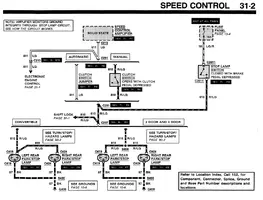
Cruise control component locations:
The servo mounts in the same location for all years 86-93. Two predrilled holes exist inside the driver's side fender to mount the servo. One vac line runs to the vacuum tree and has a check-valve inline. A cable exists the servo into the engine bay and connects to the throttle body arm. A wiring harness exits the servo and enters the interior of the car and connects to the cruise control amplifier. Another vac line enters the interior and connects to a vac switch on the brake pedal arm. This arm vents to atmosphere when the brake pedal is pressed.
(click thumbnails to enlarge)

The cruise control cable can be removed from the servo by way of two bolts. The cable extends into the engine bay, and connects to the throttle body.

The amplifier was mounted in two spots. 86-88 (possibly earlier) had the amplifier mounted to the brake pedal assembly. The mount holes for the later style 89+ bracket exist in the 87-89 cars (I believe for the 2.3 fan controller) so you can mount the amp either way here.

89-93 had the amplifier connects to the LH cowl area under the dash. The mount holes exist on the 86-88 if you choose to mount an 89+ amp with this style bracket. You’ll likely need the dash off to actually get to it however


There are two harness plugged into the amplifier. One harness connects to the servo and the other is the body harness that gets fed from the steering switch and VSS and other inputs. Wire pinouts/colors/ID in the next post
Cruise control Amplifiers:
I've identified at least two different cruise control amplifiers at this time. There may be additional P/N's. E9 refers to a 1989 engineering part number
E9ZF-9D843-BA (Yellow/white box)
E9ZF-9D843-AA (Black box)
At this time, the differences are unknown.
Suspected but not confirmed 80-86 unit
E0AF- 9D844-AA(black box)
Photo of E9ZF-9D843-AA black unit with 89-93 mount bracket

Photo of early 86-88 style mount bracket (P/N unknown)

Cruise control pedal components:
Pedal assemblies in cars with cruise control have additional components added. These parts are bolted on, and can be swapped to non-cruise assemblies. They consist of a brake pedal vac dump switch and mount, and a clutch switch and mount. The AOD's only have the brake pedal switch. The clutch switch plug on the dash harness is jumped out. Both cars feature a plastic bump stop that contacts the brake pedal switch that mounts on the brake pedal arm.

Part numbers I've found:
Clutch pedal release switch and mount:
E1DB-9F645-AC (1981- )
E9ZB-9F645-BA (1989-1993)
F4ZZ-9A837-A (1994+)
The above switches all interchange, and likely you'll find the F4 part more commonly.
 www.npdlink.com
Brake pedal vacuum dump depressor (black plastic tab on brake pedal
E62C-9C962-AB
Column harness
This info is incomplete. 85-89 cars feature a contact plate and a brush assembly. Non-cruise cars will only have 2 contact points for the horn, while cruise cars have a 3-finger brush. The part number for the 85-89 brush is E5ZZ-9C899-B and E6ZZ-9C899-B At this time I do not have info for the 90+ harnesses, but assume there may be a difference
Edit: part number E5FZ-9C899-B is also confirmed as working

1990-1992 cars use a similar "brush" with 3 fingers.
FOZZ-9C899-B 1990
F1ZZ-9C899-A 1991-1992 (superceeds prior part number)

1993 Cars use an unobtaining clockspring. F3ZC-14A664-AB. Unsure if there are cruise/non-cruise differences

This is the contact plate for the 1987-1989 cars. This mounts on the backside of the steering wheel and contacts the "brush assembly"
Part numbers i've found for these contact plates:
E53C-3L503-AA
E63C-13808-AA
E7ZC-13A808-AA
E9SC-13A808-BA

Theory of Operation:
(BTW, if you've installed LED brake lights, it interferes with how the cruise module monitors the brake light circuit. You may need to add resistors or remove the bulbs to restore function)


Main Vacuum distribution

This will cover 86-93 Mustang cruise, and is incomplete as i can't investigate every scenario.
Cruise control component locations:
The servo mounts in the same location for all years 86-93. Two predrilled holes exist inside the driver's side fender to mount the servo. One vac line runs to the vacuum tree and has a check-valve inline. A cable exists the servo into the engine bay and connects to the throttle body arm. A wiring harness exits the servo and enters the interior of the car and connects to the cruise control amplifier. Another vac line enters the interior and connects to a vac switch on the brake pedal arm. This arm vents to atmosphere when the brake pedal is pressed.
(click thumbnails to enlarge)
The cruise control cable can be removed from the servo by way of two bolts. The cable extends into the engine bay, and connects to the throttle body.
The amplifier was mounted in two spots. 86-88 (possibly earlier) had the amplifier mounted to the brake pedal assembly. The mount holes for the later style 89+ bracket exist in the 87-89 cars (I believe for the 2.3 fan controller) so you can mount the amp either way here.
89-93 had the amplifier connects to the LH cowl area under the dash. The mount holes exist on the 86-88 if you choose to mount an 89+ amp with this style bracket. You’ll likely need the dash off to actually get to it however
There are two harness plugged into the amplifier. One harness connects to the servo and the other is the body harness that gets fed from the steering switch and VSS and other inputs. Wire pinouts/colors/ID in the next post
Cruise control Amplifiers:
I've identified at least two different cruise control amplifiers at this time. There may be additional P/N's. E9 refers to a 1989 engineering part number
E9ZF-9D843-BA (Yellow/white box)
E9ZF-9D843-AA (Black box)
At this time, the differences are unknown.
Suspected but not confirmed 80-86 unit
E0AF- 9D844-AA(black box)
Photo of E9ZF-9D843-AA black unit with 89-93 mount bracket
Photo of early 86-88 style mount bracket (P/N unknown)
Cruise control pedal components:
Pedal assemblies in cars with cruise control have additional components added. These parts are bolted on, and can be swapped to non-cruise assemblies. They consist of a brake pedal vac dump switch and mount, and a clutch switch and mount. The AOD's only have the brake pedal switch. The clutch switch plug on the dash harness is jumped out. Both cars feature a plastic bump stop that contacts the brake pedal switch that mounts on the brake pedal arm.
Part numbers I've found:
Clutch pedal release switch and mount:
E1DB-9F645-AC (1981- )
E9ZB-9F645-BA (1989-1993)
F4ZZ-9A837-A (1994+)
The above switches all interchange, and likely you'll find the F4 part more commonly.
Switch Assy, Speed Control Release, Incl Wiring And Bracket, W/ Id Codes *E1db-9f645-Ac*, *E9zb-9f645-Ba*, Prior Part Number E1dz-9a837-A, F4zz-9a837-A - #M-9A837-3 - National Parts Depot
Buy part #M-9A837-3 Switch Assy, Speed Control Release, Incl Wiring And Bracket, W/ Id Codes *E1db-9f645-Ac*, *E9zb-9f645-Ba*, Prior Part Number E1dz-9a837-A, F4zz-9a837-A for your classic vehicle from National Parts Depot. Free shipping on orders over $300, fast delivery & everyday low pricing...
www.npdlink.com
Brake pedal vacuum dump depressor (black plastic tab on brake pedal
E62C-9C962-AB
Column harness
This info is incomplete. 85-89 cars feature a contact plate and a brush assembly. Non-cruise cars will only have 2 contact points for the horn, while cruise cars have a 3-finger brush. The part number for the 85-89 brush is E5ZZ-9C899-B and E6ZZ-9C899-B At this time I do not have info for the 90+ harnesses, but assume there may be a difference
Edit: part number E5FZ-9C899-B is also confirmed as working
1990-1992 cars use a similar "brush" with 3 fingers.
FOZZ-9C899-B 1990
F1ZZ-9C899-A 1991-1992 (superceeds prior part number)
1993 Cars use an unobtaining clockspring. F3ZC-14A664-AB. Unsure if there are cruise/non-cruise differences
This is the contact plate for the 1987-1989 cars. This mounts on the backside of the steering wheel and contacts the "brush assembly"
Part numbers i've found for these contact plates:
E53C-3L503-AA
E63C-13808-AA
E7ZC-13A808-AA
E9SC-13A808-BA
Theory of Operation:
(BTW, if you've installed LED brake lights, it interferes with how the cruise module monitors the brake light circuit. You may need to add resistors or remove the bulbs to restore function)
Main Vacuum distribution
Attachments

Last edited: