Hello to everyone!
I bought my first Mustang, -88 5.0 GT and I'm having some problems with it.
Biggest problem is that it doesn't seem to have all the power in it.
Also when driving in low rpm's and accelerating, the car stutters and the exhaust sound is something like papapapapapa…
Revving in stationary it sounds and works ok.
I have changed the plugs, rotor and cap, no influence.
I have also cleaned the throttle body, checked TPS and timing.
KOEO says 22,19,18 and KOER 21,45
BUT I don't get the 11 at the beginning, only one light flash before codes…
It also seems by the plugs that the car runs lean.
And the car is speed density model.
Is my ECM or wiring busted or what is the matter?
The code 22 is the first code to fix...
MAP/BARO sensor operation and code 22
Revised 14-Nov-2014 to add wire colors for frequency & voltage testing and engine sensor wiring diagrams.
On a Speed Density car, the MAP/BARO sensor is connected to the intake manifold and acts to sense the manifold pressure. Lower vacuum inside the intake manifold when combined with more throttle opening measured by the TPS means more airflow through the engine. As airflow increases, fuel flow through the injectors needs to increase to keep the air/fuel ratio where it needs to be. When manifold vacuum increases, the engine is either decelerating or idling, and it needs to reduce the fuel flow through the injectors.
On a Mass Air car, the MAP/BARO sensor vents to open air and actually senses the barometric pressure due to changes in weather and altitude. Its purpose is to set a baseline for the computer to know the barometric pressure. As barometric pressure decreases, it leans out the fuel flow to compensate for less oxygen in the air. When the barometric pressure rises, it increases to add fuel since there is more oxygen in the air. The fuel requirements decrease as altitude increases, since the atmospheric pressure decreases.
Disconnecting the MAP or BARO sensor will set code 22.
Misconnecting the BARO sensor to vacuum on a Mass Air car will cause the computer to lean out the fuel mixture.
Code 22 or 126 MAP (vacuum) or BARO signal out of range. The MAP or BARO sensor is pretty much the same sensor for both Mass Air & Speed Density cars. The main difference is where it is connected. Mass Air cars vent it to the atmosphere, while Speed Density cars connect it to the intake manifold vacuum. Its purpose is to help set a baseline for the air/fuel mixture by sensing changes in barometric pressure. The MAP or BAP sensor puts out a 5 volt square wave that changes frequency with variations in atmospheric pressure. The base is 154 HZ at 29.92" of mercury - dry sunny day at sea level, about 68-72 degrees. You need an oscilloscope or frequency meter to measure it. There a very few DVM’s with a price tag under $40 that will measure frequency, but there are some out there.
Map sensor wiring:
black/white - ground
orange/white or +5 volts power
white/red signal out.
Measure the +5 volt supply using the orange/white and black/white wires
Measure the signal using the black/white and white/red wires.
The MAP/BARO sensor is mounted on the firewall behind the upper manifold on 86-93 Mustangs.
Baro or MAP test using a real frequency meter - run the test key on, engine off. The noise from the ignition system will likely upset the frequency meter. I used a 10 x oscilloscope probe connected from the frequency meter to the MAP/BAP to reduce the jitter in the meter's readout. And oscilloscope is very useful if you have access to one or know of someone who does. With an oscilloscope, you can see the waveform and amplitude.
If it is defective, your air/fuel ratio will be off and the car’s performance & emissions will suffer
Some basic checks you can make to be sure that the sensor is getting power & ground:
Note that all resistance tests must be done with power off. Measuring resistance with a circuit powered on will give false readings and possibly damage the meter.
Check the resistance between the black/white wire on the MAP/BARO sensor and then the black/white wire on the EGR and the same wire on the TPS. It should be less than 1 ohm. Next check the resistance between the black/white wire and the negative battery cable. It should be less than 1.5 ohm.
The following power on check requires you to turn the ignition switch to the Run position.
Use a DVM to check for 5 volts on the orange/white wire. If it is missing, look for +5 volts at the orange/white wire on the TPS or EGR sensors. Use the black/white wire for the ground for the DVM.
Code 18 - SPOUT out or wiring fault - look for short to ground in SPOUT wiring going
back to the computer. Possible bad TFI or defective 22 K resistor in the IDM wiring
Use a timing light to check the timing: remove the SPOUT and observe that the timing retards at least 4 degrees. Put the SPOUT back in place and observe that the spark advances at least 4 degrees.
This code can disable spark advance and reduce power and fuel economy.
Remove the passenger side kick panel and disconnect the computer connector.
There is a 10 MM bolt that holds it in place.
Disconnect the TFI module connector from the TFI and the measure the resistance between the yellow/lt green wire and ground.
You should see greater than 100 K (100000) ohms.
Check the resistance from Pin 4 on the computer connector (dark green/yellow) and the dark green/yellow wire on the TFI connector. You should see 20-24 K Ohms (20,000-24,0000 ohms).
Resistor location: A big thanks to liljoe07 for this information:
Check over by the brake booster. Its not in the harness on the TFI, its on the main part of the harness over by the plugs that connect to the dash harness. About 6" or so from that, going back toward the EEC.
If I remember right, the resistor is covered in a shrink tubing that is sealed to the wires. So, you wont be able see any markings. The shrink tubing is labeled though. It's a 22kohm 1/2 watt resistor.
Here is the location.
Next measure the resistance between the yellow/lt green wire on the TFI module connector and Pin 36 on the computer connector. With the SPOUT plug in place, you should see less than 2 ohms.
The following is a view from the computer side of the computer connector.
This diagram is the wire side of the computer connector.
Diagram courtesy of Tmoss & Stang&2birds
Code 19 - Engine off - No Vehicle Power (pins 37 + 57) or bad PCM VPWR Diagnosis. This is a wiring problem that is from a bad ECC power relay, bad connection, bad fuse link, bad ignition switch or a bad computer. The ECC relay is located on top of the computer under the passenger side kick panel. Pull the connector off any fuel injector and measure the voltage on the red wire: if its 12 volts or better, the ECC relay is OK. If the ECC relay is OK, pull the kick panel off and measure the voltage at pins 37 & 57. If it is 12 volts or more, then the computer's diagnostic firmware has taken a dump and is defective.
Engine running - Erratic idle during test (reset throttle & retest) - Idle Set Procedures .
See
http://www.stangnet.com/mustang-forums/698148-help-me-create-surging-idle-checklist.html#post6855020 for the best way to set the mechanical base idle and cleaning procedure for the IAC/IAB.
Code 21 or 116 – ECT sensor out of range. Broken or damaged wiring, bad ECT sensor.
[color= blue]Revised 6-Apr-2017 to add diagrams and resistance check for ECT wiring.[/color]
Note that that if the outside air temp is below 50 degrees F that the test for the ECT can be in error. Warm the engine up until you get good hot air from the heater and then dump the codes again.
The computer Engine Coolant Temperature sensor has absolutely nothing to do with the temperature gauge. They are different animals. The ECT sensor is normally located it the passenger side front of the engine in the water feed tubes for the heater. It has two wires that connect by a weathertight plastic connector.
The water temperature sender for the temp gauge is located in the driver's side lower intake manifold. It has a single wire that connects by a push on connector on the temp sender.
If you have replaced the ECT sensor and are still having ECT like problem symptoms, check the ECT wiring .
Computer wiring harness connector, wire side
Computer wiring harness connector, computer side
See the graphic for the 10 pin connector circuit layout.
Check the resistance of the green wire on the ECT connector to the green wire on pin 7 of the computer connector. You should see less that 1 Ω (ohm)
The ACT & ECT have the same thermistor, so the table values are the same
ACT & ECT test data:
Use Pin 46 on the computer for ground for both ECT & ACT to get most accurate readings.
Pin 7 on the computer - ECT signal in. At 176 degrees F it should be .80 volts
Pin 25 on the computer - ACT signal in. At 50 degrees F it should be 3.5 volts. It is a good number if the ACT is mounted in the inlet airbox. If it is mounted in the lower intake manifold, the voltage readings will be lower because of the heat transfer.
Voltages may be measured across the ECT/ACT by probing the connector from the rear. A pair of safety pins may be helpful in doing this. Use care in doing it so that you don't damage the wiring or connector.
Here's the table :
50 degrees F = 3.52 v
68 degrees F = 3.02 v
86 degrees F = 2.62 v
104 degrees F = 2.16 v
122 degrees F = 1.72 v
140 degrees F = 1.35 v
158 degrees F = 1.04 v
176 degrees F = .80 v
194 degrees F = .61
212 degrees F = .47 v
230 degrees F = .36 v
248 degrees F = .28 v
Ohms measures at the computer with the computer disconnected, or at the sensor with the sensor disconnected.
50 degrees F = 58.75 K ohms
68 degrees F = 37.30 K ohms
86 degrees F = 27.27 K ohms
104 degrees F = 16.15 K ohms
122 degrees F = 10.97 K ohms
140 degrees F = 7.60 K ohms
158 degrees F = 5.37 K ohms
176 degrees F = 3.84 K ohms
194 degrees F = 2.80 K ohms
212 degrees F = 2.07 K ohms
230 degrees F = 1.55 K ohms
248 degrees F = 1.18 k ohms
Diagram courtesy of Tmoss & Stang&2birds
Wiring_Diagram.gif[/
Code 45 - (engine running) Electronic Ignition – coil primary circuit failure – Ignition Systems. Check ignition coil , coil low voltage wiring and TFI module.
Diagrams courtesy of Tmoss & Stang&2birds
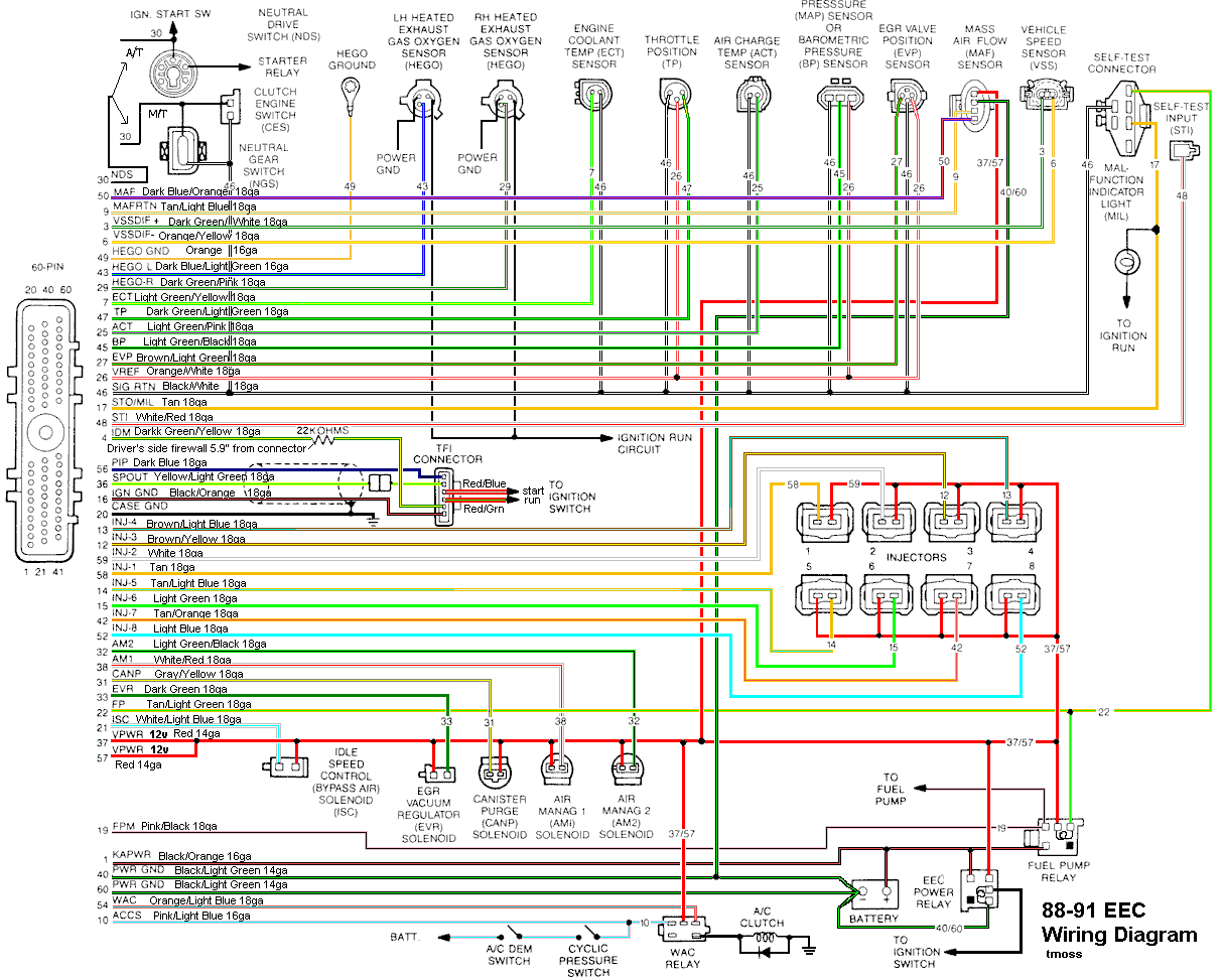
Complete computer, actuator & sensor wiring diagram for 88-91 Mass Air Mustangs
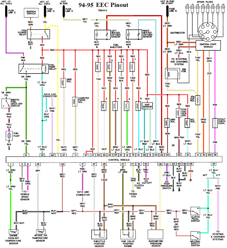
Complete computer, actuator & sensor wiring diagram for 91-93 Mass Air Mustangs
See the following website for some help from Tmoss (diagram designer) & Stang&2Birds (website host) for help on 88-95 wiring
http://www.veryuseful.com/mustang/tech/engine/ Everyone should bookmark this site.
Complete computer, actuator & sensor wiring diagram for 91-93 Mass Air Mustangs
http://www.veryuseful.com/mustang/tech/engine/images/91-93_5.0_EEC_Wiring_Diagram.gif
Complete computer, actuator & sensor wiring diagram for 88-91 Mass Air Mustangs
http://www.veryuseful.com/mustang/tech/engine/images/88-91_5.0_EEC_Wiring_Diagram.gif
Ignition switch wiring
http://www.veryuseful.com/mustang/tech/engine/images/IgnitionSwitchWiring.gif
Fuel, alternator, A/C and ignition wiring
http://www.veryuseful.com/mustang/tech/engine/images/fuel-alt-links-ign-ac.gif
O2 sensor wiring harness
http://www.veryuseful.com/mustang/tech/engine/images/mustangO2Harness.gif
Vacuum diagram 89-93 Mustangs
http://www.veryuseful.com/mustang/tech/engine/images/mustangFoxFordVacuumDiagram.jpg
HVAC vacuum diagram
http://www.veryuseful.com/mustang/tech/engine/images/Mustang_AC_heat_vacuum_controls.gif
TFI module differences & pin out
http://www.veryuseful.com/mustang/tech/engine/images/TFI_5.0_comparison.gif
Fuse box layout
http://www.veryuseful.com/mustang/tech/engine/images/MustangFuseBox.gif
87-92 power window wiring
http://www.veryuseful.com/mustang/tech/engine/images/mustang87-92 PowerWindowWiring.gif
93 power window wiring
http://www.veryuseful.com/mustang/tech/engine/images/mustang93PowerWindows.gif
T5 Cutaway showing T5 internal parts
http://www.veryuseful.com/mustang/tech/engine/images/5_Speed_Cutaway_Illustrated.jpg
Visual comparison of the Ford Fuel Injectors, picture by TMoss:
http://www.veryuseful.com/mustang/tech/engine/images/Ford_Injector_Guide.jpg