
You are using an out of date browser. It may not display this or other websites correctly.
You should upgrade or use an alternative browser.
You should upgrade or use an alternative browser.
1992 LX 5.0 mystery. use to run now doesn't. HELP
- Thread starter voodoo18
- Start date
@voodoo18
I have personally seen occasions when the engine would not start until a plug wire was disconnected and then try to start to it. I don't have a solid answer for that,
I do have a few suspicions; spray the inside and outside of the distributor cap and rotor with WD40, wait 5 minutes and them wipe them dry. I suspect that the coil spark is bypassing the rotor and finding another path to ground. The extra gap provided by the insertion of the spark tester reduces the voltage so that it does not jump to ground and goes where it is supposed to go.

Just took a code reading. 22 and 24. 22 is Manifold absolute pressure (MAP) or BARO sensor out of range. 24 can either be Intake air charge temp sensor or vane air temp sensor out of range. OR coil #1 primary circuit failure. You think I should put my original coil back on? and what does MAP have anything to do with not getting spark?
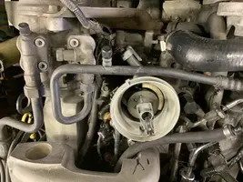
These are some of what you asked for
Attachments
-
 8BC473E7-D4DC-4F81-AC2F-2C62CB0BB6D4.webp103 KB · Views: 240
 -
 9F775AD9-6F7A-4192-B4AE-1E17FDA2038F.webp72.4 KB · Views: 240
 -
 008CC321-9674-4E30-9D16-864A56DC831C.webp71 KB · Views: 255
 -
 D394A262-253F-4BB2-9F39-CB75DCD86CD5.webp98.1 KB · Views: 244
 -
 B63524E8-C8F0-4D7B-935F-FEF507FBC76B.webp99 KB · Views: 233
Here are the rest. I have it running with the coil wire ALMOST all the way on.
Attachments
-
 1D1DF097-8752-4D8E-915D-173EEC8F57B6.webp91.3 KB · Views: 241
 -
 873A1CEB-0A51-4F7D-8600-A68ACA591D5C.webp98.1 KB · Views: 219
 -
 56DAF3E7-FC19-42BA-9F32-FE5A4479B1A6.webp102.5 KB · Views: 233
 -
 636A58BE-0035-48EB-A76E-2347A211A187.webp95.5 KB · Views: 239
 -
 360CFCF1-24C6-4897-9704-AD421557A69E.webp99.1 KB · Views: 216
I tried to send a video but the forum won’t let me. Send me an email and I will send the video. [email protected]
John. Send me an email and I will send you pix and a video. Changed the coil back to the motorcraft. I can get the wire ALMOST on before it ground out. Getting closer.
[email protected]
[email protected]
08GT500
5 Year Member
08GT500
5 Year Member
If you’re asking it that’s correct, yes, that’s how to list your video here.Post the vid on YouTube and link it here.
-John
Just took a code reading. 22 and 24. 22 is Manifold absolute pressure (MAP) or BARO sensor out of range. 24 can either be Intake air charge temp sensor or vane air temp sensor out of range. OR coil #1 primary circuit failure. You think I should put my original coil back on? and what does MAP have anything to do with not getting spark?
MAP/BARO sensor operation and code 22
Revised 24 Oct 2018 add warning about trying to measure the MAP/BARO sensor output with a common multimeter.
On a Speed Density car, the MAP/BARO sensor is connected to the intake manifold and acts to sense the manifold pressure. Lower vacuum inside the intake manifold when combined with more throttle opening measured by the TPS means more airflow through the engine. As airflow increases, fuel flow through the injectors needs to increase to keep the air/fuel ratio where it needs to be. When manifold vacuum increases, the engine is either decelerating or idling, and it needs to reduce the fuel flow through the injectors.
On a Mass Air car, the MAP/BARO sensor vents to open air and actually senses the barometric pressure due to changes in weather and altitude. Its purpose is to set a baseline for the computer to know the barometric pressure. As barometric pressure decreases, it leans out the fuel flow to compensate for less oxygen in the air. When the barometric pressure rises, it increases to add fuel since there is more oxygen in the air. The fuel requirements decrease as altitude increases, since the atmospheric pressure decreases.
Disconnecting the wiring connector from the MAP or BARO sensor will set code 22..
Misconnecting the BARO sensor to vacuum on a Mass Air car will cause the computer to lean out the fuel mixture.
Code 22 or 126 MAP (vacuum) or BARO signal out of range. The MAP or BARO sensor is pretty much the same sensor for both Mass Air & Speed Density cars. The main difference is where it is connected. Mass Air cars vent it to the atmosphere, while Speed Density cars connect it to the intake manifold vacuum. Its purpose is to help set a baseline for the air/fuel mixture by sensing changes in barometric pressure. The MAP or BAP sensor puts out a 5 volt square wave that changes frequency with variations in atmospheric pressure. The base is 154 HZ at 29.92" of mercury - dry sunny day at sea level, about 68-72 degrees. You need an oscilloscope or frequency meter to measure it. There a very few DVM’s with a price tag under $40 that will measure frequency, but there are some out there.
Map sensor wiring:
black/white - ground
orange/white or +5 volts power
white/red signal out.
Measure the +5 volt supply using the orange/white and black/white wires
Measure the signal using the black/white and white/red wires.
The MAP/BARO sensor is mounted on the firewall behind the upper manifold on 86-93 Mustangs.
The Baro or MAP sensor can only be tested using a real frequency meter. The sensor output is a square wave which cannot be accurately measured with a common multimeter. Run the test key on, engine off.. The noise from the ignition system will likely upset the frequency meter. I used a 10 x oscilloscope probe connected from the frequency meter to the MAP/BAP to reduce the jitter in the meter's readout. And oscilloscope is very useful if you have access to one or know of someone who does. With an oscilloscope, you can see the waveform and amplitude.
If it is defective, your air/fuel ratio will be off and the car’s performance & emissions will suffer
Some basic checks you can make to be sure that the sensor is getting power & ground:
Note that all resistance tests must be done with power off. Measuring resistance with a circuit powered on will give false readings and possibly damage the meter.
Check the resistance between the black/white wire on the MAP/BARO sensor and then the black/white wire on the EGR and the same wire on the TPS. It should be less than 1 ohm. Next check the resistance between the black/white wire and the negative battery cable. It should be less than 1.5 ohm.
The following power on check requires you to turn the ignition switch to the Run position.
Use a DVM to check for 5 volts on the orange/white wire. If it is missing, look for +5 volts at the orange/white wire on the TPS or EGR sensors. Use the black/white wire for the ground for the DVM.
Diagrams courtesy of Tmoss & Stang&2birds
Complete computer, actuator & sensor wiring diagram for 88-91 Mass Air Mustangs
Complete computer, actuator & sensor wiring diagram for 91-93 Mass Air Mustangs
See the following website for some help from Tmoss (diagram designer) & Stang&2Birds (website host) for help on 88-95 wiring http://www.veryuseful.com/mustang/tech/engine/ Everyone should bookmark this site.
Complete computer, actuator & sensor wiring diagram for 91-93 Mass Air Mustangs
Complete computer, actuator & sensor wiring diagram for 88-91 Mass Air Mustangs
Ignition switch wiring
Fuel, alternator, A/C and ignition wiring
O2 sensor wiring harness
Vacuum diagram 89-93 Mustangs
HVAC vacuum diagram
TFI module differences & pin out
Fuse box layout
87-92 power window wiring
93 power window wiring
T5 Cutaway showing T5 internal parts
Visual comparison of the Ford Fuel Injectors, picture by TMoss:
Code 24 - Intake Air Temperature (ACT) sensor out of range.
Bad sensor, bad wiring. The ACT for Mustangs built before 95 is in the
#5 intake runner. It measures the air temperature in the intake to help
computer the proper air/fuel ratio.
Note that that if the outside air temp is below 50 degrees F that the test for the ACT can be in error. Warm the engine up to operating temperature and retest.
ACT & ECT test data:
The ACT & ECT have the same thermistor, so the table values are the same
Pin 7 on the computer - ECT signal in. at 176 degrees F it should be .80 volts
Pin 25 on the computer - ACT signal in. at 50 degrees F it should be 3.5 volts.
It is a good number if the ACT is mounted in the inlet airbox. If it is mounted in
the lower intake manifold, the voltage readings will be lower because of the heat transfer.
Here's the table :
50 degrees F = 3.52 v
68 degrees F = 3.02 v
86 degrees F = 2.62 v
104 degrees F = 2.16 v
122 degrees F = 1.72 v
140 degrees F = 1.35 v
158 degrees F = 1.04 v
176 degrees F = .80 v
194 degrees F = .61
212 degrees F = .47 v
230 degrees F = .36 v
248 degrees F = .28 v
Ohms measures at the computer with the computer disconnected,
or at the sensor with the sensor disconnected.
50 degrees F = 58.75 K ohms
68 degrees F = 37.30 K ohms
86 degrees F = 27.27 K ohms
104 degrees F = 16.15 K ohms
122 degrees F = 10.97 K ohms
140 degrees F = 7.60 K ohms
158 degrees F = 5.37 K ohms
176 degrees F = 3.84 K ohms
194 degrees F = 2.80 K ohms
212 degrees F = 2.07 K ohms
230 degrees F = 1.55 K ohms
248 degrees F = 1.18 k ohms

Is the battery fully charged?
I ask this because of the pm you sent me about working on the window motors and running the top up and down without the engine running.
Have you looked at your ignition switch under the dash?
You may need to go back through the checklist.
I ask this because of the pm you sent me about working on the window motors and running the top up and down without the engine running.
Have you looked at your ignition switch under the dash?
You may need to go back through the checklist.
Yes. The battery is at 100% and it is new. I charge it quite often just to keep the charge up. Trying to start it take it down. I have changed the ignition switch and found a couple bad splices that I repaired.
And that is my problem. Everything I go to work on it, I go through the list.
I loosened up the distributor key in run, I have power on the + side of the coil. When I move the dis. back and forth, the fuel pump clicks on to maintain the 38-40 psi. The light blinked. As I read, that means the coil could be bad. So I put a different one, I bought it recently. The new one didn't blink, which I read that means it is good. I get a very dim spark. Could this mean that this coil is bad also?
I have checked wires until I see them in my sleep and haven't found any bad ones. I am not an electrician by trade. I don't really know the values that I am suppose to get. I will go out tomorrow and try again.
Don't think for a second that I don't appreciate this information an brain storming. It is driving me nuts.
I will get back to this when I get a chance to work on it again. Like today, I had to play with my septic tank. That was pretty crappy. Pun intended.
I forgot. As I posted on the first post. I changed to a lower resistance wire. Could this make a difference?
08GT500
5 Year Member
Hey Dave,
LTNS! Wish it were under better circumstances, still having electrical issues...
Last I recall it was the coil collapsing under the wire being solidly landed in the cap. What plugs, wires, do you have- same? New OE coil..
-John
LTNS! Wish it were under better circumstances, still having electrical issues...
Last I recall it was the coil collapsing under the wire being solidly landed in the cap. What plugs, wires, do you have- same? New OE coil..
-John
Motor craft plugs set at .55. Advanced Auto (AA) BWD coil, AA wires, 8mm. They are about half the ohms of the other ones Ford Motorsport. (could this make a difference?) New MotorCraft battery. I recharge it between work sessions. Same cap that ran, same rotor that ran. I had a BWD TFI and that crapped out so I bought the NAPA brand, recommended by a friend. New BWD pickup that I put in. The thing is, I was able to start it by long arcing the coil wire. So I know it will run. When I had the MotorCraft wires on, I had spark. I put the AA wires back on and changed the coil to the AA BWD coil and all I get is a vary faint glow in my spark tester. I have compression, just checked about 150per, and I have fuel pressure, 38 - 40. the Thing is driving my nuts. Do you think I should try a hotter than stock coil?
BTW John, I see do you have an 08 GT 500? I have one also. Convertible. Drive the heck out of it. Bought it new and have almost 70K on it. Love it.
BTW John, I see do you have an 08 GT 500? I have one also. Convertible. Drive the heck out of it. Bought it new and have almost 70K on it. Love it.
08GT500
5 Year Member
Hi Dan,
I will respond to your questions today, not sideballing ya.-k? Putting this 331 in an 89’ pony for a customer today, been waiting, parts showed, he’s driving me loopy(IER).. In the interim, the ignition system & battery flattening out is still pretty much the same situation as previous, additional parts you added is the difference vs before?
Sure we can get you going in the right direction.
Back to the checklist, see 1 G.
G.) Ignition switch - look for 12 volts at the ignition coil red/lt green wire. No 12 volts, blown fuse link or faulty ignition switch. Remove the plastic from around the ignition switch and look for 12 volts on the red/green wire on the ignition switch with it in the Run position. No 12 volts and the ignition switch is faulty. If 12 volts is present in the Run position at the ignition switch but not at the coil, then the fuse or fuse link is blown.
Note: fuses or fuse links blow for a reason. Don’t replace either a fuse or fuse link with one with a larger rating than stock. Doing so invites an electrical fire.
Ignition fuse links may be replaced with an inline fuse holder and 5 amp fuse for troubleshooting purposes.
94-95 models only: Check inside fuse panel for fuse #18 blown – 20 amp fuse
The following are diagrams courtesy of Tmoss & Stang&2birds
5.0 wiring diagram for Fuel Injectors, Sensors, and Actuators
08GT500
5 Year Member
Hi,
At this point it’s draining a new battery flat, otherwise, so you keep a float charger on it.
You've replaced the:
Coil (Advanced Auto)
TFI (NAPA)
Plugs (OE)
Wires (lower Resistance/Ft than Ford Mpsp)
Pickup inside the Dizzy
Battery
Spark is weak with the Spark tester & you are not able to get it to run at this point. ?
Still have the other parts replaced?
Best.
-John
Similar threads
- Replies
- 8
- Views
- 259
- Replies
- 7
- Views
- 199
- Replies
- 2
- Views
- 571
- Replies
- 6
- Views
- 133
- Replies
- 10
- Views
- 440