
So for anyone not knowing, I just recently swapped a 92 5.0 5 speed, into my 92 mustang. Completely swapped the harnesses (had a donor 5.0 car), hooked everything up, etc. We started it up, and it runs like garbage, way worse than it was on the donor car before we pulled it. We hooked up the charcoal canister vacuum recently, but nothing changed. We drove it out of the garage and let it idle to see if it would just clear up. The blue/grey/white exhaust smoke eventually went away. We filled up the coolant, but the dash still said "low coolant". Then, the radiator cap started steaming, and the headers were cherry red. Then, oil started leaking from behind the alternator, and near the waterpump (not sure exactly where). Car is getting on my nerves, and nothing online is solving this problem. Believe its vacuum, but I have no idea whats wrong with the vac!
You are using an out of date browser. It may not display this or other websites correctly.
You should upgrade or use an alternative browser.
You should upgrade or use an alternative browser.
Engine 4k RPM Idle, glowing headers, exhaust smoke, low coolant
- Thread starter red5.0fox
- Start date
Hey bud!
So that definitely sux...I'm feeling your pain and frustration, man. You know, it would seem there is more than one issue, and some unrelated headaches there. As for the smoke...was there an issue with the old motor? Like, problems that may have left oily pipes (blue smoke), or maybe there was some water in your pipes already (white smoke)? Could be as simple as that as far as the initial smoking is concerned. And sometimes, even a perfectly otherwise healty motor that has sat for a long time, particularly outside, will just plain smoke for a minute; pure and simple....sticky rings, condensation, hardened valve seals, etc...it might just wanna run for a while before it's warm and happy again, so I wouldn't lose hope yet. Oil leaks are their very own issue of course, and as long as the motor is in good shape, should be easy fixes. On to the glowing headers...timing, timing, timing! It sounds like it's blowing way too much fire out the pipe. Check it and make sure, but I'd be willing to bet you'll find it extremely retarded, and the computer is fighting its hardest to try to keep it in range. I highly doubt a vacuum leak is causing the bulk of your issues, though I wouldn't rule it out as being maybe a part of it as a lean condition can also wreak havoc on cylinder temps. However, those are fairly easy to locate with a can of carb cleaner, or something of the sort, sprayed anywhere a leak is possible with the motor running...it'll stumble and let you know. As for the water level issue, fill the radiator up, but leave the cap off until it gets up to temp...the thermostat will eventually open and it'll suck down a bunch more water and level out as it purges all the air out. The water level will often rise and fall while this is happening, and puke some water back OUT, until it's reached its running level; then you can put the cap back on and let it pressure up and check for leaks. The super high idle could be causing it get hot too though...it might just not cool well enough sitting still at 4000 rpm with zero air flow through the radiator. I can't imagine it having a vacuum leak large enough to cause it to idle that high without sucking the hat off your head and whistling all the neighborhood dogs into formation, so I'm thinking maybe unhook the throttle cable, or at least verify it's not pulling the throttle open, and that the butterfly is closed. Check those things first and let us know what you find. Mostly, keep it simple and be patient. If it ran good in the other car, it'll do it again...Good luck, bud!
So that definitely sux...I'm feeling your pain and frustration, man. You know, it would seem there is more than one issue, and some unrelated headaches there. As for the smoke...was there an issue with the old motor? Like, problems that may have left oily pipes (blue smoke), or maybe there was some water in your pipes already (white smoke)? Could be as simple as that as far as the initial smoking is concerned. And sometimes, even a perfectly otherwise healty motor that has sat for a long time, particularly outside, will just plain smoke for a minute; pure and simple....sticky rings, condensation, hardened valve seals, etc...it might just wanna run for a while before it's warm and happy again, so I wouldn't lose hope yet. Oil leaks are their very own issue of course, and as long as the motor is in good shape, should be easy fixes. On to the glowing headers...timing, timing, timing! It sounds like it's blowing way too much fire out the pipe. Check it and make sure, but I'd be willing to bet you'll find it extremely retarded, and the computer is fighting its hardest to try to keep it in range. I highly doubt a vacuum leak is causing the bulk of your issues, though I wouldn't rule it out as being maybe a part of it as a lean condition can also wreak havoc on cylinder temps. However, those are fairly easy to locate with a can of carb cleaner, or something of the sort, sprayed anywhere a leak is possible with the motor running...it'll stumble and let you know. As for the water level issue, fill the radiator up, but leave the cap off until it gets up to temp...the thermostat will eventually open and it'll suck down a bunch more water and level out as it purges all the air out. The water level will often rise and fall while this is happening, and puke some water back OUT, until it's reached its running level; then you can put the cap back on and let it pressure up and check for leaks. The super high idle could be causing it get hot too though...it might just not cool well enough sitting still at 4000 rpm with zero air flow through the radiator. I can't imagine it having a vacuum leak large enough to cause it to idle that high without sucking the hat off your head and whistling all the neighborhood dogs into formation, so I'm thinking maybe unhook the throttle cable, or at least verify it's not pulling the throttle open, and that the butterfly is closed. Check those things first and let us know what you find. Mostly, keep it simple and be patient. If it ran good in the other car, it'll do it again...Good luck, bud!
Last edited:
Curious if you made any progress on this?
From what you describe, I would guess timing is off and/or vac leak, and maybe a blown head gasket causing the oil leak.
Is your specific complaint that the engine overheated?
Sorry, I don’t visit this much. 4K idle was connectors in the Tachometer. After re soldering, it idles around 1k. Coolant problem was a stuck thermostat. Oil leak was also the timing cover. We replaced the distributor because the 1st was broken, and the headers aren’t glowing anymore. BUT NOW we are running codes and getting Code 14 and 18. Not sure what to do about those. Would replacing the SPOUT connector fix it? I feel like it’s something to do with the new distributor as we didn’t have that code when we ran a test before replacing it. Letting the car sit without the batter for 20 mins to try and flush the codes.
@red5.0fox
Code 14 - Ignition pickup (PIP) was erratic – the Hall Effect sensor in the distributor is failing. Bad sensor, bad wiring, dirty contacts. Factory tach will sometimes read erratically.
Revised 8-Apr-2017 to correct SPOUT problem symptoms wording
The PIP is a Hall Effect magnetic sensor that triggers the TFI and injectors. There is a shutter wheel alternately covers and uncovers a fixed magnet as it rotates. The change in the magnetic field triggers the sensor. They are often heat sensitive, increasing the failure rate as the temperature increases.
PIP Sensor functionality, testing and replacement:
The PIP is a Hall Effect magnetic sensor that triggers the TFI and injectors. There is a shutter wheel alternately covers and uncovers a fixed magnet as it rotates. The change in the magnetic field triggers the sensor. A failing PIP sensor will often set code 14 in the computer. They are often heat sensitive, increasing the failure rate as the temperature increases.
Some simple checks to do before replacing the PIP sensor or distributor:
You will need a Multimeter or DVM with good batteries: test or replace them before you get started.. You may also need some extra 16-18 gauge wire to extend the length of the meter’s test leads.
Visual check first: look for chaffed or damaged wiring and loose connector pins in the TFI harness connector.
Check the IDM wiring – dark green/yellow wire from the TFI module to pin 4 on the computer. There is a 22K Ohm resistor in the wiring between the TFI and the computer. Use an ohmmeter to measure the wire resistance from the TFI to the computer. You should see 22,000 ohms +/- 10%.
Check the PIP wiring - dark blue from the TFI module to pin 56 on the computer. Use an ohmmeter to measure the wire resistance from the TFI to the computer. You should see 0.2-1.5 ohms.
Check the SPOUT wiring – yellow/lt green from the TFI module to pin 36 on the computer. Use an ohmmeter to measure the wire resistance from the TFI to the computer. You should see 0.2-1.5 ohms.
Check the black/orange wire from the TFI module to pin 16 on the computer. Use an ohmmeter to measure the wire resistance from the TFI to the computer. You should see 0.2-1.5 ohms.
Check the red/green wire; it should have a steady 12-13 volts with the ignition switch on and the engine not running.
Check the red/blue wire; it should have a steady 12-13 volts with the ignition switch in Start and the engine not running. Watch out for the fan blades when you do this test, since the engine will be cranking.
If you do not find any chaffed or broken wires, high resistance connections or loose pins in the wiring harness, replace the PIP sensor or the distributor.
The PIP sensor is mounted in the bottom of the distributor under the shutter wheel. In stock Ford distributors, you have to press the gear off the distributor shaft to get access to it to replace it. Most guys just end up replacing the distributor with a reman unit for about $75 exchange
PIP problems & diagnostic info
Spark with the SPOUT out, but not with the SPOUT in suggests a PIP problem. The PIP signal level needs to be above 6.5 volts to trigger the computer to pulse the fuel injectors, but only needs to be 5.75 volts to trigger the TFI module. Hence with a weak PIP signal, and the SPOUT in, you could get spark but no injector pulse. You will need an oscilloscope or graphing DVM to measure the output voltage since it is not a straight DC voltage.
See http://www.wellsmfgcorp.com/pdf/counterp_v8_i2_2004.pdf and http://www.wellsmfgcorp.com/pdf/counterp_v8_i3_2004.pdf for verification of this little detail from Wells, a manufacturer of TFI modules and ignition system products.
Code 18 - SPOUT out or wiring fault - look for short to ground in SPOUT wiring going
back to the computer. Possible bad TFI or defective 22 K resistor in the IDM wiring
Revised 24 June 2019 to add comment about the need of thermal paste on TFI mounting surface.
Use a timing light to check the timing: remove the SPOUT and observe that the timing retards at least 4 degrees. Put the SPOUT back in place and observe that the spark advances at least 4 degrees.
This code can disable spark advance and reduce power and fuel economy.
Remove the passenger side kick panel and disconnect the computer connector.
It takes a 10 MM socket to remove the bolt that holds the connector in place..
Disconnect the TFI module connector from the TFI and the measure the resistance between the yellow/lt green wire and ground.
You should see greater than 100 K (100000) ohms.
Check the resistance from Pin 4 on the computer connector (dark green/yellow) and the dark green/yellow wire on the TFI connector. You should see 20-24 K Ohms (20,000-24,0000 ohms).
Resistor location: A big thanks to liljoe07 for this information:
Next measure the resistance between the yellow/lt green wire on the TFI module connector and Pin 36 on the computer connector. With the SPOUT plug in place, you should see less than 2 ohms.
The following is a view from the computer side of the computer connector.

This diagram is the wire side of the computer connector.

Diagram courtesy of Tmoss & Stang&2birds

If you replace the or remove the TFI, clean the mounting surface off with alcohol and apply a fresh coat of Thermal paste to the TFI mounting surface. Fail to do this and the TFI will quit working once the engine warms up.
Code 14 - Ignition pickup (PIP) was erratic – the Hall Effect sensor in the distributor is failing. Bad sensor, bad wiring, dirty contacts. Factory tach will sometimes read erratically.
Revised 8-Apr-2017 to correct SPOUT problem symptoms wording
The PIP is a Hall Effect magnetic sensor that triggers the TFI and injectors. There is a shutter wheel alternately covers and uncovers a fixed magnet as it rotates. The change in the magnetic field triggers the sensor. They are often heat sensitive, increasing the failure rate as the temperature increases.
PIP Sensor functionality, testing and replacement:
The PIP is a Hall Effect magnetic sensor that triggers the TFI and injectors. There is a shutter wheel alternately covers and uncovers a fixed magnet as it rotates. The change in the magnetic field triggers the sensor. A failing PIP sensor will often set code 14 in the computer. They are often heat sensitive, increasing the failure rate as the temperature increases.
Some simple checks to do before replacing the PIP sensor or distributor:
You will need a Multimeter or DVM with good batteries: test or replace them before you get started.. You may also need some extra 16-18 gauge wire to extend the length of the meter’s test leads.
Visual check first: look for chaffed or damaged wiring and loose connector pins in the TFI harness connector.
Check the IDM wiring – dark green/yellow wire from the TFI module to pin 4 on the computer. There is a 22K Ohm resistor in the wiring between the TFI and the computer. Use an ohmmeter to measure the wire resistance from the TFI to the computer. You should see 22,000 ohms +/- 10%.
Check the PIP wiring - dark blue from the TFI module to pin 56 on the computer. Use an ohmmeter to measure the wire resistance from the TFI to the computer. You should see 0.2-1.5 ohms.
Check the SPOUT wiring – yellow/lt green from the TFI module to pin 36 on the computer. Use an ohmmeter to measure the wire resistance from the TFI to the computer. You should see 0.2-1.5 ohms.
Check the black/orange wire from the TFI module to pin 16 on the computer. Use an ohmmeter to measure the wire resistance from the TFI to the computer. You should see 0.2-1.5 ohms.
Check the red/green wire; it should have a steady 12-13 volts with the ignition switch on and the engine not running.
Check the red/blue wire; it should have a steady 12-13 volts with the ignition switch in Start and the engine not running. Watch out for the fan blades when you do this test, since the engine will be cranking.
If you do not find any chaffed or broken wires, high resistance connections or loose pins in the wiring harness, replace the PIP sensor or the distributor.
The PIP sensor is mounted in the bottom of the distributor under the shutter wheel. In stock Ford distributors, you have to press the gear off the distributor shaft to get access to it to replace it. Most guys just end up replacing the distributor with a reman unit for about $75 exchange
PIP problems & diagnostic info
Spark with the SPOUT out, but not with the SPOUT in suggests a PIP problem. The PIP signal level needs to be above 6.5 volts to trigger the computer to pulse the fuel injectors, but only needs to be 5.75 volts to trigger the TFI module. Hence with a weak PIP signal, and the SPOUT in, you could get spark but no injector pulse. You will need an oscilloscope or graphing DVM to measure the output voltage since it is not a straight DC voltage.
See http://www.wellsmfgcorp.com/pdf/counterp_v8_i2_2004.pdf and http://www.wellsmfgcorp.com/pdf/counterp_v8_i3_2004.pdf for verification of this little detail from Wells, a manufacturer of TFI modules and ignition system products.
Code 18 - SPOUT out or wiring fault - look for short to ground in SPOUT wiring going
back to the computer. Possible bad TFI or defective 22 K resistor in the IDM wiring
Revised 24 June 2019 to add comment about the need of thermal paste on TFI mounting surface.
Use a timing light to check the timing: remove the SPOUT and observe that the timing retards at least 4 degrees. Put the SPOUT back in place and observe that the spark advances at least 4 degrees.
This code can disable spark advance and reduce power and fuel economy.
Remove the passenger side kick panel and disconnect the computer connector.
It takes a 10 MM socket to remove the bolt that holds the connector in place..
Disconnect the TFI module connector from the TFI and the measure the resistance between the yellow/lt green wire and ground.
You should see greater than 100 K (100000) ohms.
Check the resistance from Pin 4 on the computer connector (dark green/yellow) and the dark green/yellow wire on the TFI connector. You should see 20-24 K Ohms (20,000-24,0000 ohms).
Resistor location: A big thanks to liljoe07 for this information:
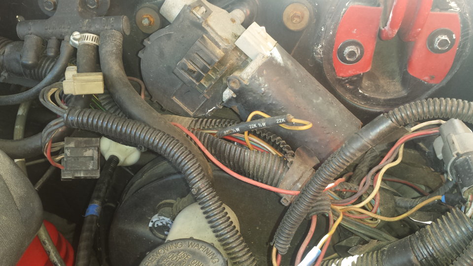
Check over by the brake booster. Its not in the harness on the TFI, its on the main part of the harness over by the plugs that connect to the dash harness. About 6" or so from that, going back toward the EEC.
If I remember right, the resistor is covered in a shrink tubing that is sealed to the wires. So, you won’t be able see any markings. The shrink tubing is labeled though. It's a 22kohm 1/2 watt resistor.
Here is the location.
Next measure the resistance between the yellow/lt green wire on the TFI module connector and Pin 36 on the computer connector. With the SPOUT plug in place, you should see less than 2 ohms.
The following is a view from the computer side of the computer connector.
This diagram is the wire side of the computer connector.
Diagram courtesy of Tmoss & Stang&2birds
If you replace the or remove the TFI, clean the mounting surface off with alcohol and apply a fresh coat of Thermal paste to the TFI mounting surface. Fail to do this and the TFI will quit working once the engine warms up.
Flushed the computer, and the codes disappeared. Did the engine running test, and now we’ve got 21, 33, and 44. Gonna buy a new temp sensor. Probably going to have to buy a new EGR valve? But now the rear main seal is leaking (likely) so gonna wait like another 2 weekends to get it finished again.Code 14 - Ignition pickup (PIP) was erratic – the Hall Effect sensor in the distributor is failing. Bad sensor, bad wiring, dirty contacts. Factory tach will sometimes read erratically.
Revised 8-Apr-2017 to correct SPOUT problem symptoms wording
The PIP is a Hall Effect magnetic sensor that triggers the TFI and injectors. There is a shutter wheel alternately covers and uncovers a fixed magnet as it rotates. The change in the magnetic field triggers the sensor. They are often heat sensitive, increasing the failure rate as the temperature increases.
PIP Sensor functionality, testing and replacement:
The PIP is a Hall Effect magnetic sensor that triggers the TFI and injectors. There is a shutter wheel alternately covers and uncovers a fixed magnet as it rotates. The change in the magnetic field triggers the sensor. A failing PIP sensor will often set code 14 in the computer. They are often heat sensitive, increasing the failure rate as the temperature increases.
Some simple checks to do before replacing the PIP sensor or distributor:
You will need a Multimeter or DVM with good batteries: test or replace them before you get started.. You may also need some extra 16-18 gauge wire to extend the length of the meter’s test leads.
Visual check first: look for chaffed or damaged wiring and loose connector pins in the TFI harness connector.
Check the IDM wiring – dark green/yellow wire from the TFI module to pin 4 on the computer. There is a 22K Ohm resistor in the wiring between the TFI and the computer. Use an ohmmeter to measure the wire resistance from the TFI to the computer. You should see 22,000 ohms +/- 10%.
Check the PIP wiring - dark blue from the TFI module to pin 56 on the computer. Use an ohmmeter to measure the wire resistance from the TFI to the computer. You should see 0.2-1.5 ohms.
Check the SPOUT wiring – yellow/lt green from the TFI module to pin 36 on the computer. Use an ohmmeter to measure the wire resistance from the TFI to the computer. You should see 0.2-1.5 ohms.
Check the black/orange wire from the TFI module to pin 16 on the computer. Use an ohmmeter to measure the wire resistance from the TFI to the computer. You should see 0.2-1.5 ohms.
Check the red/green wire; it should have a steady 12-13 volts with the ignition switch on and the engine not running.
Check the red/blue wire; it should have a steady 12-13 volts with the ignition switch in Start and the engine not running. Watch out for the fan blades when you do this test, since the engine will be cranking.
If you do not find any chaffed or broken wires, high resistance connections or loose pins in the wiring harness, replace the PIP sensor or the distributor.
The PIP sensor is mounted in the bottom of the distributor under the shutter wheel. In stock Ford distributors, you have to press the gear off the distributor shaft to get access to it to replace it. Most guys just end up replacing the distributor with a reman unit for about $75 exchange
PIP problems & diagnostic info
Spark with the SPOUT out, but not with the SPOUT in suggests a PIP problem. The PIP signal level needs to be above 6.5 volts to trigger the computer to pulse the fuel injectors, but only needs to be 5.75 volts to trigger the TFI module. Hence with a weak PIP signal, and the SPOUT in, you could get spark but no injector pulse. You will need an oscilloscope or graphing DVM to measure the output voltage since it is not a straight DC voltage.
See http://www.wellsmfgcorp.com/pdf/counterp_v8_i2_2004.pdf and http://www.wellsmfgcorp.com/pdf/counterp_v8_i3_2004.pdf for verification of this little detail from Wells, a manufacturer of TFI modules and ignition system products.
Code 18 - SPOUT out or wiring fault - look for short to ground in SPOUT wiring going
back to the computer. Possible bad TFI or defective 22 K resistor in the IDM wiring
Revised 24 June 2019 to add comment about the need of thermal paste on TFI mounting surface.
Use a timing light to check the timing: remove the SPOUT and observe that the timing retards at least 4 degrees. Put the SPOUT back in place and observe that the spark advances at least 4 degrees.
This code can disable spark advance and reduce power and fuel economy.
Remove the passenger side kick panel and disconnect the computer connector.
It takes a 10 MM socket to remove the bolt that holds the connector in place..
Disconnect the TFI module connector from the TFI and the measure the resistance between the yellow/lt green wire and ground.
You should see greater than 100 K (100000) ohms.
Check the resistance from Pin 4 on the computer connector (dark green/yellow) and the dark green/yellow wire on the TFI connector. You should see 20-24 K Ohms (20,000-24,0000 ohms).
Resistor location: A big thanks to liljoe07 for this information:
Next measure the resistance between the yellow/lt green wire on the TFI module connector and Pin 36 on the computer connector. With the SPOUT plug in place, you should see less than 2 ohms.
The following is a view from the computer side of the computer connector.
This diagram is the wire side of the computer connector.
Diagram courtesy of Tmoss & Stang&2birds
If you replace the or remove the TFI, clean the mounting surface off with alcohol and apply a fresh coat of Thermal paste to the TFI mounting surface. Fail to do this and the TFI will quit working once the engine warms up.
Code 21 or 116 – ECT sensor out of range. Broken or damaged wiring, bad ECT sensor.Flushed the computer, and the codes disappeared. Did the engine running test, and now we’ve got 21, 33, and 44. Gonna buy a new temp sensor. Probably going to have to buy a new EGR valve? But now the rear main seal is leaking (likely) so gonna wait like another 2 weekends to get it finished again.
Learn to use the codes as a guide to troubleshoot problems. Test, Observe and then Diagnose... That beats throwing parts, time, and money at a problem.
[color= blue]Revised 6-Apr-2017 to add diagrams and resistance check for ECT wiring.[/color]
Note that that if the outside air temp is below 50 degrees F that the test for the ECT can be in error. Warm the engine up until you get good hot air from the heater and then dump the codes again.
The computer Engine Coolant Temperature sensor has absolutely nothing to do with the temperature gauge. They are different animals. The ECT sensor is normally located it the passenger side front of the engine in the water feed tubes for the heater. It has two wires that connect by a weathertight plastic connector.
The water temperature sender for the temp gauge is located in the driver's side lower intake manifold. It has a single wire that connects by a push on connector on the temp sender.
If you have replaced the ECT sensor and are still having ECT like problem symptoms, check the ECT wiring .
Computer wiring harness connector, wire side
Computer wiring harness connector, computer side
See the graphic for the 10 pin connector circuit layout.
Check the resistance of the green wire on the ECT connector to the green wire on pin 7 of the computer connector. You should see less that 1 Ω (ohm)
The ACT & ECT have the same thermistor, so the table values are the same
ACT & ECT test data:
Use Pin 46 on the computer for ground for both ECT & ACT to get most accurate readings.
Pin 7 on the computer - ECT signal in. At 176 degrees F it should be .80 volts
Pin 25 on the computer - ACT signal in. At 50 degrees F it should be 3.5 volts. It is a good number if the ACT is mounted in the inlet airbox. If it is mounted in the lower intake manifold, the voltage readings will be lower because of the heat transfer.
Voltages may be measured across the ECT/ACT by probing the connector from the rear. A pair of safety pins may be helpful in doing this. Use care in doing it so that you don't damage the wiring or connector.
Here's the table :
50 degrees F = 3.52 v
68 degrees F = 3.02 v
86 degrees F = 2.62 v
104 degrees F = 2.16 v
122 degrees F = 1.72 v
140 degrees F = 1.35 v
158 degrees F = 1.04 v
176 degrees F = .80 v
194 degrees F = .61
212 degrees F = .47 v
230 degrees F = .36 v
248 degrees F = .28 v
Ohms measures at the computer with the computer disconnected, or at the sensor with the sensor disconnected.
50 degrees F = 58.75 K ohms
68 degrees F = 37.30 K ohms
86 degrees F = 27.27 K ohms
104 degrees F = 16.15 K ohms
122 degrees F = 10.97 K ohms
140 degrees F = 7.60 K ohms
158 degrees F = 5.37 K ohms
176 degrees F = 3.84 K ohms
194 degrees F = 2.80 K ohms
212 degrees F = 2.07 K ohms
230 degrees F = 1.55 K ohms
248 degrees F = 1.18 k ohms
Diagram courtesy of Tmoss & Stang&2birds


See the following website for some help from Tmoss (diagram designer) & Stang&2Birds
(website host) for help on 88-95 wiring http://www.veryuseful.com/mustang/tech/engine/
Ignition switch wiring
Fuel, alternator, A/C and ignition wiring
Complete computer, actuator & sensor wiring diagram for 88-91 Mass Air Mustangs
Vacuum diagram 89-93 Mustangs
Code 33 - Insufficient EGR flow detected.
Look for vacuum leaks, cracked vacuum lines, failed EGR vacuum regulator. Check to see if you have 10” of vacuum at the EGR vacuum connection coming from the intake manifold. Look for electrical signal at the vacuum regulator solenoid valves located on the rear of the passenger side wheel well. Using a test light across the electrical connector, it should flicker as the electrical signal changes. Remember that the computer does not source any power, but provides the ground necessary to complete the circuit. That means one side of the circuit will always be hot, and the other side will go to ground or below 1 volt as the computer switches on that circuit.
Check for resistance between the brown/lt green wire on the EGR sensor and pin 27 on the computer: you should have less than 1.5 ohm.
Backside view of the computer wiring connector:
See the following website for some help from Tmoss (diagram designer) & Stang&2Birds (website host)
http://www.veryuseful.com/mustang/tech/engine/images/fuel-alt-links-ign-ac.gif
http://www.veryuseful.com/mustang/tech/engine/images/88-91eecPinout.gif
EGR test procedure courtesy of cjones
to check the EGR valve:
bring the engine to normal temp.
connect a vacuum pump to the EGR Valve or see the EGR test jig drawing below. Connect the test jig or to directly to manifold vacuum.
Do not connect the EGR test jig to the EVR (Electronic Vacuum Regulator).
apply 5in vacuum to the valve. Using the test jig, use your finger to vary the vacuum
if engine stumbled or died then EGR Valve and passage(there is a passageway through the heads and intake) are good.
if engine did NOT stumble or die then either the EGR Valve is bad and/or the passage is blocked.
if engine stumbled, connect EGR test jig to the hose coming off of the EGR Valve.
Use your finger to cap the open port on the vacuum tee.
snap throttle to 2500 RPM (remember snap the throttle don't hold it there).
did the vacuum gauge show about 2-5 in vacuum?
if not the EVR has failed
EGR test jig
The operation of the EGR vacuum regulator can be checked by using a test light applied across the wiring connector. Jumper the computer into self test mode and turn the key on but do not start the engine. You will hear all the actuators (including the EVR vacuum regulator) cycle. Watch for the light to flicker: that means the computer has signaled the EGR vacuum regulator successfully.
Codes 44 & 94 - AIR system inoperative - Air Injection. Check vacuum lines for leaks, & cracks. Check for a clogged air crossover tube, where one or both sides of the tube clog with carbon.
Revised 21 Sep 2012 to correct the description of the process that sets the code and include Thermactor Air System diagram.
If you have a catalytic converter H pipe, you need to fix these codes. If you don't, then don't worry about them.
Code 44 passenger side air not functioning.
Code 94 driver side air not functioning.
The TAD solenoid/TAD diverter valve directs smog pump output to either the crossover tube attached to the cylinder heads or to the catalytic converters.
The O2 sensors are placed before the catalytic converters, so they do not see the extra O2 when the smog pump's output is directed to the converters or the input just before the converter.
The 44/94 code uses the O2 sensors to detect a shift in the O2 level in the exhaust. The smog pump provides extra air to the exhaust which raises the O2 level in the exhaust when the smog pump output is directed through the crossover tube.
When there is an absence of increase in the O2 levels when the TAD solenoid/TAD diverter valve directs air through the crossover tube, it detects the lower O2 level and sets the code.
Failure mode is usually due to a clogged air crossover tube, where one or both sides of the tube clog with carbon. The air crossover tube mounts on the back of the cylinder heads and supplies air to each of the Thermactor air passages cast into the cylinder heads. When the heads do not get the proper air delivery, they set codes 44 & 94, depending on which passage is clogged. It is possible to get both 44 & 94, which would suggest that the air pump or control valves are not working correctly, or the crossover tube is full of carbon or missing.
Testing the system:
Note that the engine must be running to do the tests unless stated otherwise. For safety’s sake, do test preparation like loosening clamps, disconnecting hoses and connecting things to a vacuum source with the engine off.
Disconnect the big hose from smog pump: with the engine running you should feel air output. Reconnect the smog pump hose & apply vacuum to the first vacuum controlled valve: Its purpose is to either dump the pump's output to the atmosphere or pass it to the next valve.
The next vacuum controlled valve directs the air to either the cylinder heads when the engine is cold or to the catalytic converter when the engine is warm. Disconnect the big hoses from the back side of the vacuum controlled valve and start the engine. Apply vacuum to the valve and see if the airflow changes from one hose to the next.
The two electrical controlled vacuum valves mounted on the rear of the passenger side wheel well turn the vacuum on & off under computer control. Check to see that both valves have +12 volts on the red wire. Then ground the white/red wire and the first solenoid should open and pass vacuum. Do the same thing to the light green/black wire on the second solenoid and it should open and pass vacuum.
Remember that the computer does not source power for any actuator or relay, but provides the ground necessary to complete the circuit. That means one side of the circuit will always be hot, and the other side will go to ground or below 1 volt as the computer switches on that circuit.
The following computer tests are done with the engine not running.
The computer provides the ground to complete the circuit to power the solenoid valve that turns the
vacuum on or off. The computer is located under the passenger side kick panel. Remove the kick panel & the cover over the computer wiring connector pins. Check Pin 38 Solenoid valve #1 that provides vacuum to the first Thermactor control valve for a switch from 12-14 volts to 1 volt or less. Do the same with pin 32 solenoid valve #2 that provides vacuum to the second Thermactor control valve. Turning the ignition to Run with the computer jumpered to self-test mode will cause all the actuators to toggle on and off. If after doing this and you see no switching of the voltage on and off, you can start testing the wiring for shorts to ground and broken wiring. An Ohm check to ground with the computer connector disconnected & the solenoid valves disconnected should show open circuit between the pin 32 and ground and again on pin 38 and ground. In like manner, there should be less than 1 ohm between pin 32 and solenoid valve #2 and pin 38 & Solenoid valve #1.
The following computer tests are done with the engine running.
If after checking the resistance of the wiring & you are sure that there are no wiring faults, start looking at the solenoid valves. If you disconnect them, you can jumper power & ground to them to verify operation with the engine running. Power & ground supplied should turn on the vacuum flow, remove either one and the vacuum should stop flowing.
Typical resistance of the solenoid valves is in the range of 20-70 Ohms.
See the following website for some help from Tmoss (diagram designer) & Stang&2Birds (website host)
http://www.veryuseful.com/mustang/tech/engine/images/fuel-alt-links-ign-ac.gif
http://www.veryuseful.com/mustang/tech/engine/images/88-91eecPinout.gif
If you have a catalytic converter H pipe, you need to fix these codes. If you don't, then don't worry about them
I don’t have cats, so won’t worry about those. We set timing to top dead center, but the headers are still glowing at 800-1000 rpm. EGR is definitely stuck. Don’t think that’s the big problem though. Any ideas?
Similar threads
- Replies
- 0
- Views
- 98
- Replies
- 1
- Views
- 482
- Replies
- 5
- Views
- 464
- Replies
- 0
- Views
- 743
- Replies
- 45
- Views
- 2K