I had to repair the connectors on my wiring going into the voltage regulator.
I took a picture before at the original way it was wired.
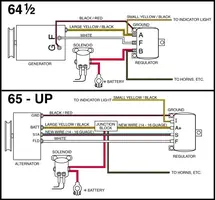
Green/Red stripe to the "F" post on the volt reg
Orange wire to the "S" post
Yellow wire to the "A" post, which also splices off to the condensor.
I hooked it back up this way and decided to check my wiring diagram in my Hayes manual.
It shows the Orange and Yellow wires switched from what I have it at now.
I was just looking for some confirmation on this.
Also the Green wire with the red strip splices off to another green/red wire with a single female bullet connector. I was wondering where this would normally go. Nothing has ever been hooked to it and it looks like the original plug.
I took a picture before at the original way it was wired.
Green/Red stripe to the "F" post on the volt reg
Orange wire to the "S" post
Yellow wire to the "A" post, which also splices off to the condensor.
I hooked it back up this way and decided to check my wiring diagram in my Hayes manual.
It shows the Orange and Yellow wires switched from what I have it at now.
I was just looking for some confirmation on this.
Also the Green wire with the red strip splices off to another green/red wire with a single female bullet connector. I was wondering where this would normally go. Nothing has ever been hooked to it and it looks like the original plug.
")