75 mustang column/ignition switch wiring diagram

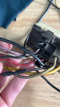
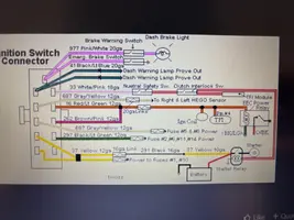
Currently doing a swap in my 1975 mustang and the wiring was all a mess. Pretty much had to cut a bunch of it out but got to gung ho and snipped the wired going to the top of the column on the ignition. I have a picture of the connector but im wondering if anyone has the diagram that shows what wires do what for when i get my engine wiring harness in. All the lights seem to be on their own separate harness. Much appreciated!
 

Attachments

  • F0F3F6C1-EDDC-4169-8286-781067C7ED60.webp
    F0F3F6C1-EDDC-4169-8286-781067C7ED60.webp
    95.3 KB · Views: 94
  • IMG_0547.webp
    IMG_0547.webp
    97.8 KB · Views: 109
I came across 2 diagrams. Ive gathered that the yellow goes to the starter relay, red/green is run, grey/yellow is crank and the black/green is accy. I just cant quite figure out what ones get connected to battery power. Im thinking from this picture its the green/black and grey/yellow. Then they must feed power to the red/green when its in the run position. Then key off kills power to red/green and shuts it all down. Let me know what you think
 

Attachments

  • IMG_0555.webp
    IMG_0555.webp
    178.9 KB · Views: 143
  • IMG_0553.webp
    IMG_0553.webp
    48.3 KB · Views: 238
  • Like
Reactions: LILCBRA