Hang on, your information bucket is about to overflow...
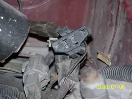
What's the little black plastic box screwed to the chassis near the left tail/brake light? Not sure if hatch vs. trunk will matter the way it's tucked back but my car's a hatch.
It is the inertia switch that shuts off the fuel pump in case of an accident.
Car runs well after the eec's been reset til it slips back into almost a limp mode, it feels like anyway.
Dumping the computer diagnostic codes on 86-95 Mustangs
Revised 26-July-2011. Added need to make sure the clutch is pressed when dumping codes.
Here's the way to dump the computer codes with only a jumper wire or paper clip and the check engine light, or test light or voltmeter. I’ve used it for years, and it works great. You watch the flashing test lamp or Check Engine Light and count the flashes.
Post the codes you get and I will post 86-93 model 5.0 Mustang specific code definitions and fixes. I do not have a complete listing for 94-95 model 5.0 Mustangs at this time.
Be sure to turn off the A/C, and put the transmission in neutral when dumping the codes. On a manual transmission car, be sure to press the clutch to the floor.
Fail to do this and you will generate a code 67 and not be able to dump the Engine Running codes.
If your car is an 86-88 stang, you'll have to use the test lamp or voltmeter method. There is no functional check engine light on the 86-88's except possibly the Cali Mass Air cars.
The STI has a gray connector shell and a white/red wire. It comes from the same bundle of wires as the self test connector.
89 through 95 cars have a working Check Engine light. Watch it instead of using a test lamp.
The STI has a gray connector shell and a white/red wire. It comes from the same bundle of wires as the self test connector.
WARNING!!! There is a single dark brown connector with a black/orange wire. It is the 12 volt power to the under the hood light. Do not jumper it to the computer test connector. If you do, you will damage the computer.
What to expect:
You should get a code 11 (two single flashes in succession). This says that the computer's internal workings are OK, and that the wiring to put the computer into diagnostic mode is good. No code 11 and you have some wiring problems.
This is crucial: the same wire that provides the ground to dump the codes provides signal ground for the TPS, EGR, ACT and Map/Baro sensors. If it fails, you will have poor performance, economy and driveablity problems
Some codes have different answers if the engine is running from the answers that it has when the engine isn't running. It helps a lot to know if you had the engine running when you ran the test.
Dumping the Engine Running codes: The procedure is the same, you start the engine with the test jumper in place. Be sure the A/C is off, and clutch (if present) is pressed to the floor, and the transmission is in neutral. You'll get an 11, then a 4 and the engine will speed up to do the EGR test. After the engine speed decreases back to idle, it will dump the engine running codes.
Trouble codes are either 2 digit or 3 digit, there are no cars that use both 2 digit codes and 3 digit codes.
Alternate methods:
For those who are intimidated by all the wires & connections, see
Actron® for what a typical hand scanner looks like. Normal retail price is about $30 or so at AutoZone or Wal-Mart.
Or for a nicer scanner see
Equus - Digital Ford Code Reader (3145) – It has a 3 digit LCD display so that you don’t have to count flashes or beeps.. Cost is $30.
Or for a nicer scanner see
http://www.midwayautosupply.com/p-7208-equus-digital-ford-code-reader-3145.aspx– It has a 3 digit LCD display so that you don’t have to count flashes or beeps.. Cost is $30.
3g alt installed incorrectly but correct now.
Stangnet 3G install sticky
http://www.stangnet.com/mustang-forums/646825-3g-alternator-install-how.html#post6673702
Facts not present in 3G installation documents
The secondary power ground is between the back of the intake manifold and the driver's side firewall. It is often missing or loose. It supplies ground for the alternator, A/C compressor clutch and other electrical accessories such as the gauges.
Any car that has a 3G or high output current alternator needs a 4 gauge ground wire running from the block to the chassis ground where the battery pigtail ground connects. The 3G has a 130 amp capacity, so you wire the power side with 4 gauge wire. It stands to reason that the ground side handles just as much current, so it needs to be 4 gauge too.
The picture shows the common ground point for the battery , computer, & extra 3G alternator ground wire as described above in paragraph 2. A screwdriver points to the bolt that is the common ground point.
The battery common ground is a 10 gauge pigtail with the computer ground attached to it.
Picture courtesy timewarped1972
Correct negative battery ground cable.
3.) The computer has its own dedicated power ground that comes off the ground pigtail on the battery ground wire. Due to its proximity to the battery, it may become corroded by acid fumes from the battery.
In 86-90 model cars, it is a black cylinder about 2 1/2" long by 1" diameter with a black/lt green wire.
In 91-95 model cars it is a black cylinder about 2 1/2" long by 1" diameter with a black/white wire.
You'll find it up next to the starter solenoid where the wire goes into the wiring harness.
4.) All the sensors have a common separate ground. This includes the TPS, ACT, EGE, BAP, & VSS sensors.
5.) The O2 sensor heaters have their own ground (HEGO ground) coming from the computer. This is different and separate from the O2 sensor ground. It is an orange wire with a ring terminal on it. It is located in the fuel injector wiring harness and comes out under the throttle body. It gets connected to a manifold or bolt on back of the cylinder head.
6.) The TFI module has 2 grounds: one for the foil shield around the wires and another for the module itself. The TFI module ground terminates inside the computer.
7.) The computer takes the shield ground for the TFI module and runs it from pin 20 to the chassis near the computer.
8.) The computer's main power ground (the one that comes from the battery ground wire) uses pins 40 & 60 for all the things it controls internally.
See http://assets.fluke.com/appnotes/automotive/beatbook.pdf for help for help troubleshooting voltage drops across connections and components. .
Wiring diagrams and troubleshooting aids
See the following website for some help from Tmoss (diagram designer) & Stang&2Birds (website host) for help on 88-95 wiring
Mustang FAQ - Wiring & Engine Info Everyone should bookmark this site.
Ignition switch wiring
http://www.veryuseful.com/mustang/tech/engine/images/IgnitionSwitchWiring.gif
Fuel, alternator, A/C and ignition wiring
http://www.veryuseful.com/mustang/tech/engine/images/fuel-alt-links-ign-ac.gif
Complete computer, actuator & sensor wiring diagram for 88-91 Mass Air Mustangs
http://www.veryuseful.com/mustang/tech/engine/images/88-91_5.0_EEC_Wiring_Diagram.gif
Complete computer, actuator & sensor wiring diagram for 91-93 Mass Air Mustangs
http://www.veryuseful.com/mustang/tech/engine/images/91-93_5.0_EEC_Wiring_Diagram.gif
Vacuum diagram 89-93 Mustangs
http://www.veryuseful.com/mustang/tech/engine/images/mustangFoxFordVacuumDiagram.jpg
HVAC vacuum diagram
http://www.veryuseful.com/mustang/tech/engine/images/Mustang_AC_heat_vacuum_controls.gif
TFI module differences & pinout
http://www.veryuseful.com/mustang/tech/engine/images/TFI_5.0_comparison.gif
Fuse box layout
http://www.veryuseful.com/mustang/tech/engine/images/MustangFuseBox.gif