@85Punisher
Maybe this will help... It's for later model Fox Mustangs, but some of the wring will be the same.
Look for a red/green wire on the ignition switch. That should be the switched power feed for the ignition coil.
The following are diagrams courtesy of Tmoss & Stang&2birds
Ignition switch wiring
See the following website for some help from Tmoss (diagram designer) & Stang&2Birds (website host) for help on 88-95 wiring; http://www.veryuseful.com/mustang/tech/engine/ Everyone should bookmark this site.
TFI module wiring for 94-95 Mustang GT
http://www.veryuseful.com/mustang/tech/engine/images/Mustang-94-95-IgnitionControlModule.gif
Complete computer, actuator & sensor wiring diagram for 94-95 Mustangs
Complete computer, actuator & sensor wiring diagram for 91-93 Mass Air Mustangs
Complete computer, actuator & sensor wiring diagram for 88-90 Mass Air Mustangs
5.0 wiring diagram for Fuel Injectors, Sensors, and Actuators
Ignition switch wiring
O2 sensor wiring harness
Vacuum diagram 89-93 Mustangs
HVAC vacuum diagram
TFI module differences & pin out
Fuse box layout
Mustang 5.0 Lights and Radio schematic, by TMoss:
http://www.veryuseful.com/mustang/tech/engine/images/mustangFoxLights-Radio_diag.gif
87-92 power window wiring
93 power window wiring
T5 Cutaway showing T5 internal parts
Visual comparison of the Ford Fuel Injectors, picture by TMoss:
Convertible top motor wiring
http://www.veryuseful.com/mustang/tech/engine/images/mustang88VertTopMotorCkt.gif
Engine mounted fuel injector harness
Location of the TPS, IAB, and the 10-pin connectors on a 5.0, picture by TMoss:
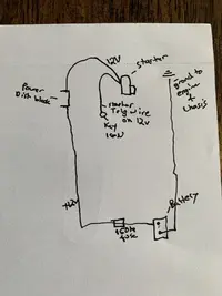
Starter circuit
Alternator diagram for 94-95 Mustangs.