Here's a book that will get you started with how the Ford electronic engine control or "computer" works.
Ford Fuel Injection & Electronic Engine Control 1988-1993 by Charles Probst :ISBN 0-8376-0301-3.
It's about $25-$35 from Borders.com see
Amazon.com: Online Shopping for Electronics, Apparel, Computers, Books, DVDs & more . Select books and then select search. Use the ISBN number (without dashes or spaces) to do a search
Use the ISBN number and your local library can get you a loaner copy for free. Only thing is you are limited to keeping the book for two weeks. It is very good, and I found it to be very helpful.
If you need some help with your automotive electrical skills, try
Automotive Online Instruction for a beginning course. The course is very good and best of all, it is FREE!!!
Since this is a Mass Air (AKA MAF) conversion, make sure the MAP sensor has the vacuum line disconnected. Cap the disconnected line. The MAP/Baro sensor is a small black box mounted on the middle of the firewall behind the upper intake manifold. On Mass Air cars the MAP sensor is used as a Baro sensor and vents to the open air.
Fix the problem that is causing the check engine light to come on first. The cam has nothing to do with the engine running rich unless it isn't an HO firing order cam.
Dumping The computer diagnostic codes on 86-95 Mustangs
Revised 19-May-2009 to update drawing for dumping the codes on 86-88 Mustangs with no check engine light.
Dump the codes and see what the computer says is wrong…
Codes may be present in the computer even if the Check Engine light isn’t on.
Here's the way to dump the computer codes with only a jumper wire or paper clip and the check engine light, or test light or voltmeter. I’ve used it for years, and it works great. You watch the flashing test lamp or Check Engine Light and count the flashes.
Be sure to turn off the A/C, and put the transmission in neutral when dumping the codes. Fail to do this and you will generate a code 67 and not be able to dump the Engine Running codes.
Dumping the Engine Running codes: The procedure is the same, you start the engine with the test jumper in place. Be sure the A/C is off and the transmission is in neutral. You'll get an 11, then a 4 and the engine will speed up to do the EGR test. After the engine speed decreases back to idle, it will dump the engine running codes.
Here's the link to dump the computer codes with only a jumper wire or paper clip and the check engine light, or test light or voltmeter. I’ve used it for years, and it works great. You watch the flashing test lamp or Check Engine Light and count the flashes.
See
Troublcodes.net Trouble Codes OBD & OBD2 Trouble Codes and Technical info & Tool Store. By BAT Auto Technical
If your car is an 86-88 stang, you'll have to use the test lamp or voltmeter method. There is no functional check engine light on the 86-88's except possibly the Cali Mass Air cars.
The STI has a gray connector shell and a white/red wire. It comes from the same bundle of wires as the self test connector.
89 through 95 cars have a working Check Engine light. Watch it instead of using a test lamp.
The STI has a gray connector shell and a white/red wire. It comes from the same bundle of wires as the self test connector.
WARNING!!! There is a single dark brown connector with a black/orange wire. It is the 12 volt power to the under the hood light. Do not jumper it to the computer test connector. If you do, you will damage the computer.
What to expect:
You should get a code 11 (two single flashes in succession). This says that the computer's internal workings are OK, and that the wiring to put the computer into diagnostic mode is good. No code 11 and you have some wiring problems.
Codes have different answers if the engine is running from the answers that it has when the engine isn't running. It helps a lot to know if you had the engine running when you ran the test.
Trouble codes are either 2 digit or 3 digit, there are no cars that use both 2 digit codes and 3 digit codes.
Alternate methods:
For those who are intimidated by all the wires & connections, see
Actron® for what a typical hand scanner looks like. Normal retail price is about $30 or so at AutoZone or Wal-Mart.
Or for a nicer scanner see
Digital Ford Code Reader (3145) – It has a 3 digit LCD display so that you don’t have to count flashes or beeps.. Cost is $30.
Fix the ACT: it helps get the air/fuel mixture correct.
There is supposed be a tapped hole for the ACT in the driver's side front lower intake runner. You will have to have the manifold off the engine and on the workbench to drill & tap it. The ACT uses a 37/64" or 9/16" drill and a 3/8" pipe tap. See
Industrial Supply Equipment from MSC Industrial Supply or
McMaster-Carr if you can't find the drill bit or tap locally.
The next best spot for the ACT is the air box if you don't do the drill and tap thing. You get to cut and splice the 2 ACT wires in order to make them long enough to reach the air box. Solder the wire extensions on the existing wires & use heat shrink tubing to cover the splices. Offset the place where you cut the wires so that you don't have a big bulge when you put heat shrink over the 2 wires to cover & protect them. The air box gets a hole (5/8" or so) for the ACT drilled about 1 1/4" down & 1/1/4" in on the front top side near the upper radiator hose. A brass fitting nut from Home Depot or Ace Hardware secures the ACT into the air box.
If you are very clever, you will find that the ACT connector comes apart so that you can remove the pins. A very small screwdriver releases the lock in the front of the center insert, while another small screwdriver inserted in the back pushes it out. Once the center insert is out of the connector shell, the pins come out easily. New pins are available from AutoZone in a $5 electrical pin kit for Fords. Crimping the pins on the extender wires saves you from having to splice them twice: once to put the connector on and once to extend the wires.
6 ft black 18 gauge wire
6 ft green 18 gauge wire
6 ft 1/4" heat shrink tubing
1 ft 3/16" heat shrink tubing
Measure the 2 extender wires & cut them to length, crimp one set of pins on them. Then mate up the extender pins with the wiring harness & slide the 3/16" heat shrink tubing over them & shrink the tubing. Then slide the 1/4" heat shrink tubing over the pair of wires and shrink the tubing. When you are done you'll have about 1" of wire left without heat shrink tubing on it to strip & crimp the new pins on. Stick the new pins in the old connector shell, assemble it and you are done. It looks as good as factory. Some wire loom can be used to enhance the "Factory Look".
Removing the emissions equipment on 5.0 Mustangs is a bad idea.
The pollution control equipment all shuts off at wide open throttle, so the HP losses from it on the car are 2-5 HP. The catalytic converters may soak a few more HP than that. None of the pollution control equipment reduces the HP enough to cost you a race in anything but all out professional drag strip competition like "Pinks".
If you removed the smog pump and still have catalytic converters, they will ultimately clog and fail.
Some basic theory to clarify how things work is in order…
EGR System theory and testing
The EGR shuts off at Wide Open Throttle (WOT), so it has minimal effect on performance. The addition of exhaust gas drops
combustion temperature, increases gas mileage and reduces the tendency of the engine to ping. It can also reduce HC emissions
by reducing fuel consumption. The primary result of EGR usage is a reduction in NOx emissions.
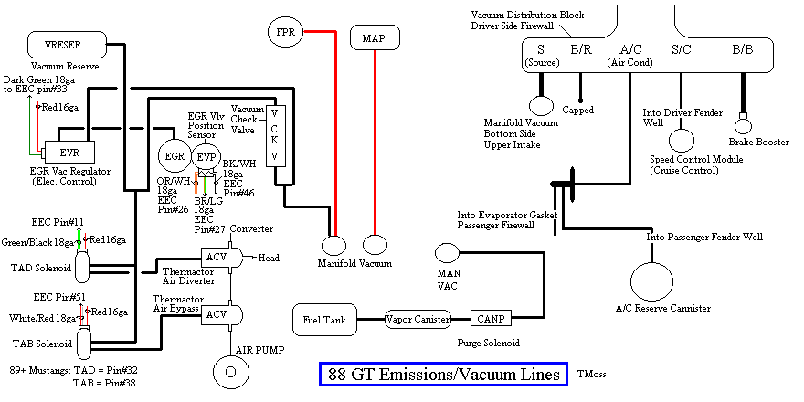
The EGR system has a vacuum source (line from the intake manifold) that goes to the EVR, computer operated electronic vacuum
regulator. The EVR is located on the back of the passenger side shock strut tower. The computer uses RPM, Load. and some other
factors to tell the EVR to pass vacuum to open the EGR valve. The EGR valve and the passages in the heads and intake manifold
route exhaust gas to the EGR spacer (throttle body spacer). The EGR sensor tells the computer how far the EGR valve is open.
Then computer adjusts the signal sent to the EVR to hold, increase or decrease the vacuum. The computer adds spark advance to
compensate for the recirculated gases and the slower rate they burn at.
Troubleshooting:
There should be no vacuum at the EGR valve when at idle. If there is, the EVR (electronic vacuum regulator) mounted on the
backside of the passenger side wheelwell is suspect. Check the vacuum line plumbing to make sure the previous owner didn’t
cross the vacuum lines.
Diagram courtesy of Tmoss & Stang&2birds. (the diagram says 88 GT, but the EGR part is the same for 86-93 Mustangs)
The EGR sensor is basically a variable resistor, like the volume control on a radio. One end is 5 volt VREF power from the
computer (red/orange wire). One end is computer signal ground (black/white), and the middle wire (brown/lt green) is the signal
output from the EGR sensor. It is designed to always have some small voltage output from it anytime the ignition switch is the
Run position. That way the computer knows the sensor & the wiring is OK. No voltage on computer pin 27 (brown/lt green wire)
and the computer thinks the sensor is bad or the wire is broken and sets code 31. The voltage output can range from approximately
.6-.85 volt.
The EVR regulates vacuum to the EGR valve to maintain the correct amount of vacuum. The solenoid coil should measure 20-70
Ohms resistance. The regulator has a vacuum feed on the bottom which draws from the intake manifold. The other vacuum line is
regulated vacuum going to the EGR valve. One side of the EVR electrical circuit is +12 volts anytime the ignition switch is in the
run position. The other side of the electrical circuit is the ground path and is controlled by the computer. The computer switches
the ground on and off to control the regulator solenoid.
EGR test procedure courtesy of cjones
EGR test procedure courtesy of cjones
to check the EGR valve:
bring the engine to normal temp.
connect a vacuum pump to the EGR Valve or
see the EGR test jig drawing below. Connnect the test jig or to directly to manifold vacuum.
Do not connect the EGR test jig to the EVR (Electronic Vacuum Regulator).
apply 5in vacuum to the valve.
Using the test jig, use your finger to vary the vacuum
if engine stumbled or died then EGR Valve and passage(there is a passageway through the heads and intake) are good.
if engine did NOT stumble or die then either the EGR Valve is bad and/or the passage is blocked.
if engine stumbled,
connect EGR test jig to the hose coming off of the EGR Valve.
Use your finger to cap the open port on the vacuum tee.
snap throttle to 2500 RPM (remember snap the throttle don't hold it there).
did the vacuum gauge show about 2-5 in vacuum?
if not the EVR has failed
EGR test jig
To test the computer, you can use a test light across the EVR wiring connectors and dump the codes. When you dump the codes,
the computer does a self test that toggles every relay/actuator/solenoid on and off. When this happens, the test light will flicker.
Late Model Restoration has the Ford Racing M-12071-N302 kit with the EGR valve & sensor along with the ACT & ECT sensors for
$45. See
* * * N/A * * * 86-93 Sensor Kit, 5.0L Efi, Includes Egr Valve & Sensor, Coolant Temp Sensor, & Air Charge Temp Sensor at LRS - Same Day Shipping! for
more details
Thermactor Air System
Some review of how it works...
The Thermactor air pump (smog pump) supplies air to the heads or catalytic converters. This air helps break down the excess HC (hydrocarbons) and CO (carbon monoxide). The air supplied to the catalytic converters helps create the catalytic reaction that changes the HC & CO into CO2 and water vapor. Catalytic converters on 5.0 Mustangs are designed to use the extra air provided by the smog pump. Without the extra air, the catalytic converters will clog and fail.
The Thermactor air pump draws air from an inlet filter in the front of the pump. The smog pump puts air into the heads when the engine is cold and then into the catalytic converters when it is warm. The Thermactor control valves serve to direct the flow. The first valve, TAB (Thermactor Air Bypass) or AM1 valve) either dumps air to the atmosphere or passes it on to the second valve. The second valve, TAD (Thermactor Air Diverter valve or AM2 valve) directs it to the heads or the catalytic converters. Check valves located after the TAB & TAD solenoids prevent hot exhaust gases from damaging the control valves or pump in case of a backfire. The air serves to help consume any unburned hydrocarbons by supplying extra oxygen to the catalytic process. The computer tells the Thermactor Air System to open the Bypass valve at WOT (wide open throttle) minimizing engine drag. This dumps the pump's output to the atmosphere, and reduces the parasitic drag caused by the smog pump to about 2-4 HP at WOT. The Bypass valve also opens during deceleration to reduce or prevent backfires.
The computer uses the change in the O2 sensor readings to detect operation of the Thermactor control valves. When the dump valve opens, it reduces the O2 readings in the exhaust system. Then it closes the dump valve and the O2 readings increase. By toggling the dump valve (TAB) and switching the diverter valve (TAD) flow from the back of the heads to the air pipe, the computer tests for the 44/94 codes.
Computer operation & control for the Thermactor Air System
Automobile computers use current sink technology. They do not source power to any relay, solenoid or actuator like the IAC, fuel pump relay, or fuel injectors. Instead the computer provides a ground path for the positive battery voltage to get back to the battery negative terminal. That flow of power from positive to negative is what provides the energy to make the IAC, fuel pump relay, or fuel injectors work. No ground provided by the computer, then the actuators and relays don't operate.
One side of the any relay/actuator/solenoid in the engine compartment will be connected to a red wire that has 12-14 volts anytime the ignition switch is in the run position. The other side will have 12-14 volts when the relay/actuator/solenoid isn't turned on. Once the computer turns on the clamp side, the voltage on the computer side of the wire will drop down to 1 volt or less.
In order to test the TAD/TAB solenoids, you need to ground the white/red wire on the TAB solenoid or the light green/black wire on the TAD solenoid.
For 94-95 cars: the colors are different. The White/Red wire (TAB control) is White/Orange (Pin 31 on the PCM). The Green/Black wire (TAD control) should be Brown (pin 34 at the PCM). Thanks to HISSIN50 for this tip.
To test the computer, you can use a test light across the TAB or TAD wiring connectors and dump the codes. When you dump the codes, the computer does a self test that toggles every relay/actuator/solenoid on and off. When this happens, the test light will flicker.
Theory of operation:
Catalytic converters consist of two different types of catalysts: Reduction and Oxidation.
The Reduction catalyst is the first converter in a 5.0 Mustang, and the Oxidation converter is the second converter. The Oxidation converter uses the extra air from the smog pump to burn the excess HC. Aftermarket converters that use the smog pump often combine both types of catalysts in one housing.
Now for the Chemistry...
"The reduction catalyst is the first stage of the catalytic converter. It uses platinum and rhodium to help reduce the NOx emissions. When an NO or NO2 molecule contacts the catalyst, the catalyst rips the nitrogen atom out of the molecule and holds on to it, freeing the oxygen in the form of O2. The nitrogen atoms bond with other nitrogen atoms that are also stuck to the catalyst, forming N2. For example:
2NO => N2 + O2 or 2NO2 => N2 + 2O2
The oxidation catalyst is the second stage of the catalytic converter. It reduces the unburned hydrocarbons and carbon monoxide by burning (oxidizing) them over a platinum and palladium catalyst. This catalyst aids the reaction of the CO and hydrocarbons with the remaining oxygen in the exhaust gas. For example:
2CO + O2 => 2CO2
There are two main types of structures used in catalytic converters -- honeycomb and ceramic beads. Most cars today use a honeycomb structure." Quote courtesy of How Stuff Works (
HowStuffWorks "Catalysts")
What happens when there is no extra air from the smog pump...
As engines age, the quality of tune decreases and wear causes them to burn oil. We have all seem cars that go down the road puffing blue or black smoke from the tailpipe. Oil consumption and poor tune increase the amount of HC the oxidation catalyst has to deal with. The excess HC that the converters cannot oxidize due to lack of extra air becomes a crusty coating inside the honeycomb structure. This effectively reduces the size of the honeycomb passageways and builds up thicker over time and mileage. Continuous usage under such conditions will cause the converter to fail and clog. The extra air provided by the Thermactor Air System (smog pump) is essential for the oxidation process. It oxidizes the added HC from oil consumption and poor tune and keeps the HC levels within acceptable limits.
Newer catalytic converters do not use the Thermactor Air System (smog pump) because they are designed to work with an improved computer system that runs leaner and cleaner
They add an extra set of O2 sensors after the catalytic converters to monitor the oxygen and HC levels. Using this additional information, the improved computer system adjusts the air/fuel mixture for cleaner combustion and reduced emissions. If the computer cannot compensate for the added load of emissions due to wear and poor tune, the catalytic converters will eventually fail and clog. The periodic checks (smog inspections) are supposed to help owners keep track of problems and get them repaired.
Firing order and HO cam check:
This doesn’t prove that the block has an HO cam. Some trucks evidently use a HO firing order
with a low lift cam. However, it will definitely prove that a cam can’t be HO because the firing order is wrong.
Remove the #1 & #3 spark plugs. Put your finger in #1 spark plug hole. Crank the engine over until you feel compression on #1 cylinder. Slowly turn the engine until the TDC mark and the timing pointer line up. Mark TDC on the balancer with chalk or paint. Put your finger in #3 spark plug hole and crank the engine 90 degrees. You should feel pressure trying to blow past your finger. If you do not feel pressure, repeat the process again. If you feel pressure, it is a HO engine.
No pressure the second time, remove spark plug #5. Put your finger in #1 spark plug hole. Crank the engine over until you feel compression on #1 cylinder. Put your finger in #5 spark plug hole and crank the engine 90 degrees. If you feel pressure now, the engine is not a HO model, no matter what it says on the engine.
Using a small carpenter or machinist square to mark the harmonic balancer off into 90 degree sections may be helpful here.
A 15/16 deep socket & breaker bar or ratchet may be used to turn the engine.
The HO firing order is 1-3-7-2-6-5-4-8.
Non HO firing order is 1-5-4-2-6-3-7-8