
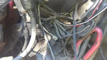
I have two connectors that are still unknown to me despite scouring wiring diagrams. I got a twin blk/w with a female spade attached to it, and i have a round 2 pin plug with blk/gr & blk/ylw (yes tied to my red grounds) wires coming out of it. Any expertice would be appreciated, thanks in advance.
You are using an out of date browser. It may not display this or other websites correctly.
You should upgrade or use an alternative browser.
You should upgrade or use an alternative browser.
89 mustang wiring concerns
- Thread starter Jacobwaring
- Start date


PM me your email address and I will send you a complete Ford Factory 89 Mustang electrical diagram set. The zip file is 2.5 MB and is too big to fit through Stangnet's email gateway.
The plug shapes on the diagrams match the plug shapes on the actual plug. The diagram is divided up by the layout of the car. The first diagram is for the very front of the car, and it works its way to the rear of the car page by page.
They are in a zip file format to reduce the size of the package. If you don't have Windows 7 or Windows 8, or later, you’ll need WinZip or other Windows archive tool to extract them from the zip file.. See www.majorgeeks.com - Download Freeware and Shareware Computer Utilities for a free download.
You will need the Adobe Acrobat viewer which is also a free download – www.adobe.com/products/acrobat/readstep2.html - Adobe Reader download - All versions
Grounds
This checklist applies to all Mustangs , not just the EFI equipped cars. Some of the wiring will be different on carb cars and carb conversions
Revised 26 –Oct -2016 to add fuel pump ground to the list.
Grounds are important to any electrical system, and especially to computer controlled engines. In an automobile, the ground is the return path for power to get back to the alternator and battery.
Make sure that all the ground places are clean and shiny bare metal: no paint, no corrosion.
1.) The main power ground is from engine block down by the oil filter to battery: it is the power ground for the starter & alternator.
2.) The secondary power ground is between the back of the intake manifold and the driver's side firewall. It is often missing or loose. It supplies ground for the alternator, A/C compressor clutch and other electrical accessories such as the gauges. The clue to a bad ground here is that the temp gauge goes up as you add electrical load such as heater, lights and A/C.
Any car that has a 3G or high output current alternator needs a 4 gauge ground wire running from the block to the chassis ground where the battery pigtail ground connects. The 3G has a 130 amp capacity, so you wire the power side with 4 gauge wire. It stands to reason that the ground side handles just as much current, so it needs to be 4 gauge too.
The picture shows the common ground point for the battery , computer, & extra 3G alternator ground wire as described above in paragraph 2. A screwdriver points to the bolt that is the common ground point.
The battery common ground is a 10 gauge pigtail with the computer ground attached to it.
Picture courtesy timewarped1972

Correct negative battery ground cable.

3.) The computer's main power ground (the one that comes from the battery ground wire) uses pins 40 & 60 for all the things it controls internally: it comes off the ground pigtail on the battery ground wire. Due to its proximity to the battery, it may become corroded by acid fumes from the battery.
In 86-90 model cars, it is a black cylinder about 2 1/2" long by 1" diameter with a black/lt green wire.
In 91-95 model cars it is a black cylinder about 2 1/2" long by 1" diameter with a black/white wire.
You'll find it up next to the starter solenoid where the wire goes into the wiring harness.
All the grounds listed in items 1,2 & 3 need to bolt to clean, shiny bare metal. A wire brush or some fine sandpaper is the best thing to use to clean the ground connections.
4.) All the sensors have a common separate signal ground. This includes the TPS, ACT, EGR, BAP, & VSS sensors. This ground is inside the computer and connects pin 46 to pins 40 & 60, which are the main computer grounds. If this internal computer ground gets damaged, you won't be able to dump codes and the car will have idle/stall/ performance problems
5.) The O2 sensor heaters have their own ground (HEGO ground) coming from the computer. This is different and separate from the O2 sensor ground. It is an orange wire with a ring terminal on it. It is located in the fuel injector wiring harness and comes out under the throttle body. It gets connected to a manifold or bolt on back of the cylinder head.
6.) The TFI module has 2 grounds: one for the foil shield around the wires and another for the module itself. The TFI module ground terminates inside the computer.
7.) The computer takes the shield ground for the TFI module and runs it from pin 20 to the chassis near the computer.
8.) Fuel pump ground the fuel pump has a ground pigtail the connects to the body under the gas tank. You have to drop the gas tank to see where it bolts to the body.

See http://assets.fluke.com/appnotes/automotive/beatbook.pdf for help troubleshooting voltage drops across connections and components. Be sure to have the maximum load on a circuit when testing voltage drops across connections. As current across a defective or weak connection, increases so does the voltage drop. A circuit or connection may check out good with no load or minimal load, but show up bad under maximum load conditions. .
Voltage drops should not exceed the following:
200 mV Wire or cable
300 mV Switch
100 mV Ground
0 mV to <50 mV Sensor Connections
0.0V bolt together connections

]
Extra grounds are like the reserve parachute for a sky diver. If the main one fails, there is always your reserve.
The best plan is to have all the grounds meet at one central spot and connect together there. That eliminates any voltage drops from grounds connected at different places. A voltage drop between the computer ground and the alternator power ground will effectively reduce the voltage available to the computer by the amount of the drop.
The plug shapes on the diagrams match the plug shapes on the actual plug. The diagram is divided up by the layout of the car. The first diagram is for the very front of the car, and it works its way to the rear of the car page by page.
They are in a zip file format to reduce the size of the package. If you don't have Windows 7 or Windows 8, or later, you’ll need WinZip or other Windows archive tool to extract them from the zip file.. See www.majorgeeks.com - Download Freeware and Shareware Computer Utilities for a free download.
You will need the Adobe Acrobat viewer which is also a free download – www.adobe.com/products/acrobat/readstep2.html - Adobe Reader download - All versions
Grounds
This checklist applies to all Mustangs , not just the EFI equipped cars. Some of the wiring will be different on carb cars and carb conversions
Revised 26 –Oct -2016 to add fuel pump ground to the list.
Grounds are important to any electrical system, and especially to computer controlled engines. In an automobile, the ground is the return path for power to get back to the alternator and battery.
Make sure that all the ground places are clean and shiny bare metal: no paint, no corrosion.
1.) The main power ground is from engine block down by the oil filter to battery: it is the power ground for the starter & alternator.
2.) The secondary power ground is between the back of the intake manifold and the driver's side firewall. It is often missing or loose. It supplies ground for the alternator, A/C compressor clutch and other electrical accessories such as the gauges. The clue to a bad ground here is that the temp gauge goes up as you add electrical load such as heater, lights and A/C.
Any car that has a 3G or high output current alternator needs a 4 gauge ground wire running from the block to the chassis ground where the battery pigtail ground connects. The 3G has a 130 amp capacity, so you wire the power side with 4 gauge wire. It stands to reason that the ground side handles just as much current, so it needs to be 4 gauge too.
The picture shows the common ground point for the battery , computer, & extra 3G alternator ground wire as described above in paragraph 2. A screwdriver points to the bolt that is the common ground point.
The battery common ground is a 10 gauge pigtail with the computer ground attached to it.
Picture courtesy timewarped1972
Correct negative battery ground cable.
3.) The computer's main power ground (the one that comes from the battery ground wire) uses pins 40 & 60 for all the things it controls internally: it comes off the ground pigtail on the battery ground wire. Due to its proximity to the battery, it may become corroded by acid fumes from the battery.
In 86-90 model cars, it is a black cylinder about 2 1/2" long by 1" diameter with a black/lt green wire.
In 91-95 model cars it is a black cylinder about 2 1/2" long by 1" diameter with a black/white wire.
You'll find it up next to the starter solenoid where the wire goes into the wiring harness.
All the grounds listed in items 1,2 & 3 need to bolt to clean, shiny bare metal. A wire brush or some fine sandpaper is the best thing to use to clean the ground connections.
4.) All the sensors have a common separate signal ground. This includes the TPS, ACT, EGR, BAP, & VSS sensors. This ground is inside the computer and connects pin 46 to pins 40 & 60, which are the main computer grounds. If this internal computer ground gets damaged, you won't be able to dump codes and the car will have idle/stall/ performance problems
5.) The O2 sensor heaters have their own ground (HEGO ground) coming from the computer. This is different and separate from the O2 sensor ground. It is an orange wire with a ring terminal on it. It is located in the fuel injector wiring harness and comes out under the throttle body. It gets connected to a manifold or bolt on back of the cylinder head.
6.) The TFI module has 2 grounds: one for the foil shield around the wires and another for the module itself. The TFI module ground terminates inside the computer.
7.) The computer takes the shield ground for the TFI module and runs it from pin 20 to the chassis near the computer.
8.) Fuel pump ground the fuel pump has a ground pigtail the connects to the body under the gas tank. You have to drop the gas tank to see where it bolts to the body.
See http://assets.fluke.com/appnotes/automotive/beatbook.pdf for help troubleshooting voltage drops across connections and components. Be sure to have the maximum load on a circuit when testing voltage drops across connections. As current across a defective or weak connection, increases so does the voltage drop. A circuit or connection may check out good with no load or minimal load, but show up bad under maximum load conditions. .
Voltage drops should not exceed the following:
200 mV Wire or cable
300 mV Switch
100 mV Ground
0 mV to <50 mV Sensor Connections
0.0V bolt together connections
]
Extra grounds are like the reserve parachute for a sky diver. If the main one fails, there is always your reserve.
The best plan is to have all the grounds meet at one central spot and connect together there. That eliminates any voltage drops from grounds connected at different places. A voltage drop between the computer ground and the alternator power ground will effectively reduce the voltage available to the computer by the amount of the drop.
Made sure the ground behind the intake is nice and clean. I found the blk/grn wire for the computer, its already grounded but i removed and cleaned. Im triple grounded at the drivers side of the motor so i know my motor is grounded lol. Ill look at that wiring diagram for that twin blk/w wire. Tested pin 46 at computer and at diagnostic port, has ground. Found my resistor that goes to the tfi has no resistance, i havent seen a resistor burn through and increase continuity but i guess anything is possible. Also found after finding bad resistor i ripped out the dizzy to test found the tfi mod d1,2,3 to h5 are about 1-4k ohm low of what its supposed to be, ill assume my pip is  too and just buy another dizzy.
Koeo code 34, 41, 91
Swapped o2s, they were old and crusty. Codes 41 & 91 returned regardless but runs better. Checked vaccuum at egr, made sure egr fuctions and kills car, this will be the third egr pos sensor i put on the car. Even w. Egr blocked off w plate still misses and stumbles so not egr.
Koer code 85 (ran over my charcoal canister putting my procharger on so there is no solenoid) 41, 18. 18 is what prompted me to check that resistor, the lingering 41 code is concerning. Could that code 41 be caused by the broken dizzy & resistor? Or am i going to be pulling xover tubes.
too and just buy another dizzy.Koeo code 34, 41, 91
Swapped o2s, they were old and crusty. Codes 41 & 91 returned regardless but runs better. Checked vaccuum at egr, made sure egr fuctions and kills car, this will be the third egr pos sensor i put on the car. Even w. Egr blocked off w plate still misses and stumbles so not egr.
Koer code 85 (ran over my charcoal canister putting my procharger on so there is no solenoid) 41, 18. 18 is what prompted me to check that resistor, the lingering 41 code is concerning. Could that code 41 be caused by the broken dizzy & resistor? Or am i going to be pulling xover tubes.
Last edited:
I did a carb cleaner test for the code 41 just to be sure, it had a hard time idling as is, but spraying everything down I saw no change in rpms. I relocated the 02 ground as it was unsatisfactory with no change.
Last edited:
Code 41 or 91. Or 43 Three digit code 172 or 176 - O2 sensor indicates system lean. Look for a vacuum leak or failing O2 sensor.
Revised 20-July-2017 to add note that the 94-95 uses a 4 wire O2 sensor.
Code 41 is the passenger side sensor, as viewed from the driver's seat.
Code 91 is the driver side sensor, as viewed from the driver's seat.
Code 172 is the passenger side sensor as viewed from the driver's seat.
Code 176 is the driver side sensor, as viewed from the driver's seat.
Code 43 is not side specific according to the Probst Ford Fuel injection book.
The computer sees a lean mixture signal coming from the O2 sensors and tries to compensate by adding more fuel. Many times the end result is an engine that runs pig rich and stinks of unburned fuel.
The following is a Quote from Charles O. Probst, Ford fuel Injection & Electronic Engine control:
"When the mixture is lean, the exhaust gas has oxygen, about the same amount as the ambient air. So the sensor will generate less than 400 Millivolts. Remember lean = less voltage.
When the mixture is rich, there's less oxygen in the exhaust than in the ambient air , so voltage is generated between the two sides of the tip. The voltage is greater than 600 millivolts. Remember rich = more voltage.
Here's a tip: the newer the sensor, the more the voltage changes, swinging from as low as 0.1 volt to as much as 0.9 volt. As an oxygen sensor ages, the voltage changes get smaller and slower - the voltage change lags behind the change in exhaust gas oxygen.
Because the oxygen sensor generates its own voltage, never apply voltage and never measure resistance of the sensor circuit. To measure voltage signals, use an analog voltmeter with a high input impedance, at least 10 megohms. Remember, a digital voltmeter will average a changing voltage." End Quote
Testing the O2 sensors 87-93 5.0 Mustangs
Measuring the O2 sensor voltage at the computer will give you a good idea of how well they are working. You'll have to pull the passenger side kick panel off to gain access to the computer connector. Remove the plastic wiring cover to get to the back side of the wiring. Use a safety pin or paper clip to probe the connections from the rear.
Disconnect the O2 sensor from the harness and use the body side O2 sensor harness as the starting point for testing. Do not measure the resistance of the O2 sensor , you may damage it. Resistance measurements for the O2 sensor harness are made with one meter lead on the O2 sensor harness and the other meter lead on the computer wire or pin for the O2 sensor.
Computer wiring harness connector, computer side.

Backside view of the computer wiring connector:

87-90 5.0 Mustangs:
Computer pin 43 Dark blue/Lt green – LH O2 sensor
Computer pin 29 Dark Green/Pink – RH O2 sensor
The computer pins are 29 (L\RH O2 with a dark green/pink wire) and 43 (LH O2 with a dark blue/pink wire). Use the ground next to the computer to ground the voltmeter. The O2 sensor voltage should switch between .2-.9 volt at idle.
91-93 5.0 Mustangs:
Computer pin 43 Red/Black – LH O2 sensor
Computer pin 29 Gray/Lt blue – RH O2 sensor
The computer pins are 29 (LH O2 with a Gray/Lt blue wire) and 43 (RH O2 with a Red/Black wire). Use the ground next to the computer to ground the voltmeter. The O2 sensor voltage should switch between .2-.9 volt at idle.
Testing the O2 sensors 94-95 5.0 Mustangs; note that the 94-95 uses a 4 wire O2 sensor.
Measuring the O2 sensor voltage at the computer will give you a good idea of how well they are working. You'll have to pull the passenger side kick panel off to gain access to the computer connector. Remove the plastic wiring cover to get to the back side of the wiring. Use a safety pin or paper clip to probe the connections from the rear. The computer pins are 29 (LH O2 with a red/black wire) and 27 (RH O2 with a gray/lt blue wire). Use pin 32 (gray/red wire) to ground the voltmeter. The O2 sensor voltage should switch between .2-.9 volt at idle.
Note that all resistance tests must be done with power off. Measuring resistance with a circuit powered on will give false readings and possibly damage the meter. Do not attempt to measure the resistance of the O2 sensors, it may damage them.
Testing the O2 sensor wiring harness
Most of the common multimeters have a resistance scale. Be sure the O2 sensors are disconnected and measure the resistance from the O2 sensor body harness to the pins on the computer. Using the Low Ohms range (usually 200 Ohms) you should see less than 1.5 Ohms.
87-90 5.0 Mustangs:
Computer pin 43 Dark blue/Lt green – LH O2 sensor
Computer pin 29 Dark Green/Pink – RH O2 sensor
Disconnect the connector from the O2 sensor and measure the resistance:
From the Dark blue/Lt green wire in the LH O2 sensor harness and the Dark blue/Lt green wire on the computer pin 43
From the Dark Green/Pink wire on the RH Os sensor harness and the Dark Green/Pink wire on the computer pin 29
91-93 5.0 Mustangs:
Computer pin 43 Red/Black – LH O2 sensor
Computer pin 29 Gray/Lt blue – RH O2 sensor
Disconnect the connector from the O2 sensor and measure the resistance:
From the Red/Black wire in the LH O2 sensor harness and the Red/Black wire on the computer pin 43
From the Dark Green/Pink Gray/Lt blue wire on the RH Os sensor harness and the Gray/Lt blue wire on the computer pin 29
94-95 5.0 Mustangs:
Computer pin 29 Red/Black – LH O2 sensor
Computer pin 27 Gray/Lt blue – RH O2 sensor
From the Red/Black wire in the LH O2 sensor harness and the Red/Black wire on the computer pin 29
From the Dark Green/Pink Gray/Lt blue wire on the RH Os sensor harness and the Gray/Lt blue wire on the computer pin 27
There is a connector between the body harness and the O2 sensor harness. Make sure the connectors are mated together, the contacts and wiring are not damaged and the contacts are clean and not coated with oil.
The O2 sensor ground (orange wire with a ring terminal on it) is in the wiring harness for the fuel injection wiring. I grounded mine to one of the intake manifold bolts
Check the fuel pressure – the fuel pressure is 37-41 PSI with the vacuum disconnected and the engine idling. Fuel pressure out of range can cause the 41 & 91 codes together. It will not cause a single code, only both codes together.
Make sure you have the proper 3 wire O2 sensors. Only the 4 cylinder cars used a 4 wire sensor, which is not compatible with the V8 wiring harness. The exception is that the 94-95 uses a 4 wire O2 sensor.
Replace the O2 sensors in pairs if replacement is indicated. If one is weak or bad, the other one probably isn't far behind.
Code 41 can also be due to carbon plugging the driver’s side Thermactor air crossover tube on the back of the engine. The tube fills up with carbon and does not pass air to the driver’s side head ports. This puts an excess amount of air in the passenger side exhaust and can set the code 41. Remove the tube and clean it out so that both sides get good airflow: this may be more difficult than it sounds. You need something like a mini rotor-rooter to do the job because of the curves in the tube. Something like the outer spiral jacket of a flexible push-pull cable may be the thing that does the trick.
If you get only code 41 and have changed the sensor, look for vacuum leaks. This is especially true if you are having idle problems. The small plastic tubing is very brittle after many years of the heating it receives. Replace the tubing and check the PVC and the hoses connected to it.
Revised 20-July-2017 to add note that the 94-95 uses a 4 wire O2 sensor.
Code 41 is the passenger side sensor, as viewed from the driver's seat.
Code 91 is the driver side sensor, as viewed from the driver's seat.
Code 172 is the passenger side sensor as viewed from the driver's seat.
Code 176 is the driver side sensor, as viewed from the driver's seat.
Code 43 is not side specific according to the Probst Ford Fuel injection book.
The computer sees a lean mixture signal coming from the O2 sensors and tries to compensate by adding more fuel. Many times the end result is an engine that runs pig rich and stinks of unburned fuel.
The following is a Quote from Charles O. Probst, Ford fuel Injection & Electronic Engine control:
"When the mixture is lean, the exhaust gas has oxygen, about the same amount as the ambient air. So the sensor will generate less than 400 Millivolts. Remember lean = less voltage.
When the mixture is rich, there's less oxygen in the exhaust than in the ambient air , so voltage is generated between the two sides of the tip. The voltage is greater than 600 millivolts. Remember rich = more voltage.
Here's a tip: the newer the sensor, the more the voltage changes, swinging from as low as 0.1 volt to as much as 0.9 volt. As an oxygen sensor ages, the voltage changes get smaller and slower - the voltage change lags behind the change in exhaust gas oxygen.
Because the oxygen sensor generates its own voltage, never apply voltage and never measure resistance of the sensor circuit. To measure voltage signals, use an analog voltmeter with a high input impedance, at least 10 megohms. Remember, a digital voltmeter will average a changing voltage." End Quote
Testing the O2 sensors 87-93 5.0 Mustangs
Measuring the O2 sensor voltage at the computer will give you a good idea of how well they are working. You'll have to pull the passenger side kick panel off to gain access to the computer connector. Remove the plastic wiring cover to get to the back side of the wiring. Use a safety pin or paper clip to probe the connections from the rear.
Disconnect the O2 sensor from the harness and use the body side O2 sensor harness as the starting point for testing. Do not measure the resistance of the O2 sensor , you may damage it. Resistance measurements for the O2 sensor harness are made with one meter lead on the O2 sensor harness and the other meter lead on the computer wire or pin for the O2 sensor.
Computer wiring harness connector, computer side.
Backside view of the computer wiring connector:
87-90 5.0 Mustangs:
Computer pin 43 Dark blue/Lt green – LH O2 sensor
Computer pin 29 Dark Green/Pink – RH O2 sensor
The computer pins are 29 (L\RH O2 with a dark green/pink wire) and 43 (LH O2 with a dark blue/pink wire). Use the ground next to the computer to ground the voltmeter. The O2 sensor voltage should switch between .2-.9 volt at idle.
91-93 5.0 Mustangs:
Computer pin 43 Red/Black – LH O2 sensor
Computer pin 29 Gray/Lt blue – RH O2 sensor
The computer pins are 29 (LH O2 with a Gray/Lt blue wire) and 43 (RH O2 with a Red/Black wire). Use the ground next to the computer to ground the voltmeter. The O2 sensor voltage should switch between .2-.9 volt at idle.
Testing the O2 sensors 94-95 5.0 Mustangs; note that the 94-95 uses a 4 wire O2 sensor.
Measuring the O2 sensor voltage at the computer will give you a good idea of how well they are working. You'll have to pull the passenger side kick panel off to gain access to the computer connector. Remove the plastic wiring cover to get to the back side of the wiring. Use a safety pin or paper clip to probe the connections from the rear. The computer pins are 29 (LH O2 with a red/black wire) and 27 (RH O2 with a gray/lt blue wire). Use pin 32 (gray/red wire) to ground the voltmeter. The O2 sensor voltage should switch between .2-.9 volt at idle.
Note that all resistance tests must be done with power off. Measuring resistance with a circuit powered on will give false readings and possibly damage the meter. Do not attempt to measure the resistance of the O2 sensors, it may damage them.
Testing the O2 sensor wiring harness
Most of the common multimeters have a resistance scale. Be sure the O2 sensors are disconnected and measure the resistance from the O2 sensor body harness to the pins on the computer. Using the Low Ohms range (usually 200 Ohms) you should see less than 1.5 Ohms.
87-90 5.0 Mustangs:
Computer pin 43 Dark blue/Lt green – LH O2 sensor
Computer pin 29 Dark Green/Pink – RH O2 sensor
Disconnect the connector from the O2 sensor and measure the resistance:
From the Dark blue/Lt green wire in the LH O2 sensor harness and the Dark blue/Lt green wire on the computer pin 43
From the Dark Green/Pink wire on the RH Os sensor harness and the Dark Green/Pink wire on the computer pin 29
91-93 5.0 Mustangs:
Computer pin 43 Red/Black – LH O2 sensor
Computer pin 29 Gray/Lt blue – RH O2 sensor
Disconnect the connector from the O2 sensor and measure the resistance:
From the Red/Black wire in the LH O2 sensor harness and the Red/Black wire on the computer pin 43
From the Dark Green/Pink Gray/Lt blue wire on the RH Os sensor harness and the Gray/Lt blue wire on the computer pin 29
94-95 5.0 Mustangs:
Computer pin 29 Red/Black – LH O2 sensor
Computer pin 27 Gray/Lt blue – RH O2 sensor
From the Red/Black wire in the LH O2 sensor harness and the Red/Black wire on the computer pin 29
From the Dark Green/Pink Gray/Lt blue wire on the RH Os sensor harness and the Gray/Lt blue wire on the computer pin 27
There is a connector between the body harness and the O2 sensor harness. Make sure the connectors are mated together, the contacts and wiring are not damaged and the contacts are clean and not coated with oil.
The O2 sensor ground (orange wire with a ring terminal on it) is in the wiring harness for the fuel injection wiring. I grounded mine to one of the intake manifold bolts
Check the fuel pressure – the fuel pressure is 37-41 PSI with the vacuum disconnected and the engine idling. Fuel pressure out of range can cause the 41 & 91 codes together. It will not cause a single code, only both codes together.
Make sure you have the proper 3 wire O2 sensors. Only the 4 cylinder cars used a 4 wire sensor, which is not compatible with the V8 wiring harness. The exception is that the 94-95 uses a 4 wire O2 sensor.
Replace the O2 sensors in pairs if replacement is indicated. If one is weak or bad, the other one probably isn't far behind.
Code 41 can also be due to carbon plugging the driver’s side Thermactor air crossover tube on the back of the engine. The tube fills up with carbon and does not pass air to the driver’s side head ports. This puts an excess amount of air in the passenger side exhaust and can set the code 41. Remove the tube and clean it out so that both sides get good airflow: this may be more difficult than it sounds. You need something like a mini rotor-rooter to do the job because of the curves in the tube. Something like the outer spiral jacket of a flexible push-pull cable may be the thing that does the trick.
If you get only code 41 and have changed the sensor, look for vacuum leaks. This is especially true if you are having idle problems. The small plastic tubing is very brittle after many years of the heating it receives. Replace the tubing and check the PVC and the hoses connected to it.
Saleen0679
10 Year Member
I have two connectors that are still unknown to me despite scouring wiring diagrams. I got a twin blk/w with a female spade attached to it, and i have a round 2 pin plug with blk/gr & blk/ylw (yes tied to my red grounds) wires coming out of it. Any expertice would be appreciated, thanks in advance.
The double BK/W wires are used to test the windshield washer pump. Usually there is a grey connector shell around them. The round 2-pin plug is likely to be part of the A/C harness. An extension harness connects the plug to the compressor.

Similar threads
- Replies
- 7
- Views
- 213
- Replies
- 0
- Views
- 564
- Replies
- 4
- Views
- 962
- Replies
- 14
- Views
- 3K
- Replies
- 8
- Views
- 6K