
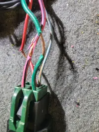
Here are photos of the O2 wiring harness and pulled back the tape and sheathing. It is in bad shape. You can see the purple wires which has the jumper on the left. Any idea what year harness this is for?
You are using an out of date browser. It may not display this or other websites correctly.
You should upgrade or use an alternative browser.
You should upgrade or use an alternative browser.
Electrical 93 LX Fuel Pump Issues w Relay & Fuse Link
- Thread starter diesel farmer
- Start date


Sounds like your pin 46 trace is burned. Time to open the ECU up and have a peek.
Problem is, if you rebuild the ECU, and stick it back in your car, you might fry it again. You still have an issue “in the field” so to speak.
Can you power the vehicle up? You don’t need to start the car, but with the ECU disconnected, put your meter on the pin46 wire in the ECU connector and ground and turn the key to on. Do you have voltage?
Here are photos of the O2 wiring harness and pulled back the tape and sheathing. It is in bad shape. You can see the purple wires which has the jumper on the left. Any idea what year harness this is for?
Purple/yellow jumper in that position means it’s a 88-90 5-spd o2 harness. 91+ was a blue jumper.
Not good if running an AOD ECU.
So I took a peek at my wiring diagrams and think I figured out something you can test to help narrow down the year of this harness.
The wiring on your fuel pump relay changed colors in 1991. 1990 and older used one color scheme and 1991 and later used another.
1990 and older used:
Orange/light blue: main power
Pink/black: feed to pump
Tan/light green: relay ground
Red/black: relay power
1991 and later
Pink/black: main power
Dark green/yellow: feed to pump
Light blue/orange: relay ground
Red: relay power.
I can’t see the wire colors clearly, so which do you have?
1990 & older

1991 & newer

The wiring on your fuel pump relay changed colors in 1991. 1990 and older used one color scheme and 1991 and later used another.
1990 and older used:
Orange/light blue: main power
Pink/black: feed to pump
Tan/light green: relay ground
Red/black: relay power
1991 and later
Pink/black: main power
Dark green/yellow: feed to pump
Light blue/orange: relay ground
Red: relay power.
I can’t see the wire colors clearly, so which do you have?
1990 & older
1991 & newer
Can you power the vehicle up? You don’t need to start the car, but with the ECU disconnected, put your meter on the pin46 wire in the ECU connector and ground and turn the key to on. Do you have voltage? I have very little voltage, ~ .02 volts from pin 46 to ground with key on.
I also already replaced the three capacitors on the A9P ECM and that didn't seem to help, although my soldering skills are less than stellar.
Purple/yellow jumper in that position means it’s a 88-90 5-spd o2 harness. 91+ was a blue jumper. Not good if running an AOD ECU. Would it be prudent to try an A9L ECM in this 93 car with a T5 manual and what appears to be an 88-90 O2 harness?
Open the ECU up again and check the backside near the 60pin connector. Look for a burned trace like this

If you do not have continuity from pin 46 to pin 40/60 chances are it’s toast.
I wouldn’t blindly stick a $300-500 A9L in there and fire it up without really digging into your harnesses and making sure it’s all corrct.
If you do not have continuity from pin 46 to pin 40/60 chances are it’s toast.
I wouldn’t blindly stick a $300-500 A9L in there and fire it up without really digging into your harnesses and making sure it’s all corrct.
That harness is likely a 1991, early 92 harness, as the fuel pump relay went underhood then.
But you have an 88-90 o2 harness.
But you have an 88-90 o2 harness.

Yup, that’s a burned trace.
The repair would be to solder a jumper across the two pins on each side of the trace, like so.

Or just send it off to ECU exchange to repair. However, if you have an A9L you should use the ECU that matches the trans. You just need to verify the wiring also matches.
Back to the o2 harness. If you plug it into the main engine harness, do the wire colors (other than the jumper) match up? Also does the jumper actually connect to two wires? The 91+ 5-speed engine harness is different than the 90 older so the wires will be different.
The repair would be to solder a jumper across the two pins on each side of the trace, like so.
Or just send it off to ECU exchange to repair. However, if you have an A9L you should use the ECU that matches the trans. You just need to verify the wiring also matches.
Back to the o2 harness. If you plug it into the main engine harness, do the wire colors (other than the jumper) match up? Also does the jumper actually connect to two wires? The 91+ 5-speed engine harness is different than the 90 older so the wires will be different.
On the O2 harness where it connects to the engine harness: 1) the wire colors do not match; and 2) on the opposite end of the jumper wires, the wires coming out of the engine harness are purple with yellow stripe and a yellow with purple stripe
Attachments

Boostedpimp
20+ Year Stangneter 
You have to remember as well that ecuexchange doesn't just upgrade the capacitors. They test the board and repair/replace the power supply as well as voltage regulators so if you have a burnt trace. Sure you could add in your own jumper wire which may totally get you on your way but you may still have issues. I think they were $100 for the service and shipping last time I delt with it just an fyi.

At this point I have a two pronged approach: #1 figure out if the car wiring is working properly; and #2 get an A9L refurbished by a reputable repair shop like the ecu-exchange. #2 is easy; #1 will be the challenge!
Since I am (a little) more confident about what wiring harnesses are in the car, I can work on getting wiring diagrams and going through the motions of tracing wires.
And Thanks to all that have provided feedback on this forum.
Since I am (a little) more confident about what wiring harnesses are in the car, I can work on getting wiring diagrams and going through the motions of tracing wires.
And Thanks to all that have provided feedback on this forum.
The below post was from Jrichker on May 27, 2014 in a thread. If I have an A9L and the 02 harness wired properly, maybe I'll be good to go.
The trace inside the computer burns up for 2 reasons:
1.) When someone dumped the codes, they used the brown connector instead of the gray one to dump the codes. The brown connector is for the under hood light and has 12 volts on it, this burns up the trace inside the computer.
2.) Auto trans O2 sensor harness was used with an A9L computer.
O2 Sensor harness interchange and modification
Originally Posted by 302EFI
Revised 16-Oct-2011 to add O2 sensor harness warnings
The wires for the 02's and low oil did not change throughout the years, they are all in the same place.
The main ones you need to worry about are (on the harness end (ECU) that plugs into the 02 plug) is:
\- 1. Lightblue / yellow
- 2. White / Purple
- 3. Purple / Yellow
The White/Purple & Purple/Yellow gets looped for a automatic ECU
The Purple/Yellow & Lightblue/Yellow for a manual ECU
See http://forums.corral.net/forums/gen...manual-auto-differences-year-differences.html for more O2 sensor wiring harness info
Basic premise to use with transmission swaps:
Only run a 5 speed trans O2 harness with an A9L. Do not run an Auto O2 sensor harness with an A9L. Doing so will damage the computer’s internal signal ground.
Only run an Auto trans O2 sensor harness with an A9P in a car that has an Auto trans. Using a 5 speed trans O2 sensor harness with an Auto trans will cause no crank problems. There has been some debate about the no crank problem,and I haven't personally checked it out.
See http://www.stangnet.com/mustang-forums/749974-computer-issue.html#post7490537 for Joel5.0’s fix to the computer internal signal ground.
90 model year harness only works with 90 model cars without inspection/rework.
The 4 cylinder O2 harness uses 4 wire O2 sensors. It probably won’t work correctly without modifying it.
On the O2 harness where it connects to the engine harness: 1) the wire colors do not match; and 2) on the opposite end of the jumper wires, the wires coming out of the engine harness are purple with yellow stripe and a yellow with purple stripe
DOes this match up to what you have? We've confirmed that O2 sensor harness is from a 88-90 5-spd, but I'm trying to determine what the mating engine harness is from.
I believe for 1991+, the engine side of the harness will not have a purple/yellow wire and instead have two Blue/yellow wires. Basically wire 771 below would be LB/Y for 91+

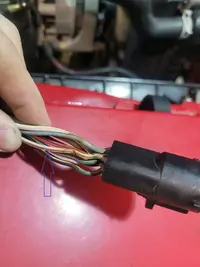
So two white purple wires that would loop together on an AOD harness. That makes sense. I’m going to guess this is a 1991+ harness.
The fact that the fuel pump relay is under the seat and not in the engine bay makes me think 91-early 1992. To confirm, one of those white/purple wires (like 771) should have continuity back to pin 30 on the ECU 60-pin connector. On a 5-spd the loop should go to the blue/yellow wire. On AOD it goes to the other white/purple
O2 sensor harness was wrong though.
Really strange though. Whatever you do, before you put another ECU in and fire it up, make sure you have no voltage on pin 30. That will fry the manual ECU
So you think someone put a year 1991 AOD engine harness into this factory 5 speed 5.0, correct?
I checked pin 30 on the ECU harness connector in the car and I don't have any continuity from it to the white-purple wires in the 02 connector -- the only pin in the 02 engine harness connector with continuity to pin 30 in the ECU harness connector is the dark blue with yellow stripe wire. Does this make sense?
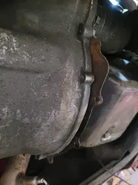
See also the pic of the existing block/spacer plate which is obviously not correct for this T5 application.
I checked pin 30 on the ECU harness connector in the car and I don't have any continuity from it to the white-purple wires in the 02 connector -- the only pin in the 02 engine harness connector with continuity to pin 30 in the ECU harness connector is the dark blue with yellow stripe wire. Does this make sense?
See also the pic of the existing block/spacer plate which is obviously not correct for this T5 application.
Attachments
Similar threads
- Replies
- 7
- Views
- 239
- Replies
- 4
- Views
- 160
- Replies
- 8
- Views
- 263
- Replies
- 8
- Views
- 406