Start by checking the fuel pump filter, fuel pressure and then the fuel pump wiring...
Something to build during the wintertime...
Fuel pressure test gauge - underhood only;
Fuel pressure gauge adapter fittings
http://www.holley.com/products.asp?product=17945NOS AN 4 to 1/16” pipe
http://www.holley.com/products.asp?product=16785NOS 1/16” male pipe to 1/8” female pipe
Or
See
Accessories - Adapters, Fitting & Hose
I made my own pressure gauge and holder. I bought the NOS or Autometer adapter that you screw into the place on the fuel line where the Schrader valve goes. You have to remove the Schrader valve, but save it, since you will reuse it. I ran a piece of SS (stainless steel) braided hose to a 1/8” pipe brass tee fitting that I mounted on the fender well by the MAF. I made a mount bracket out of aluminum angle I got from Home depot and bolted it to the fender well. Then I mounted the brass tee to it with some machine screws and a plate. I sandwiched the brass tee between the aluminum angle and a flat piece of aluminum that I trimmed off the extra aluminum angle. Three screws laid out in a triangle pattern go through both pieces of aluminum to clamp the tee in place. Put the Schrader valve in the spare port of the brass tee. I used a cheap industrial gauge from MSC Direct (
MSC Industrial Supply Co. | Find Power Tools, Hand Tools, Machine Tools & More P/N 56468499). It works great and was cheaper than (less than $8) anything Summit had.
If you look through the MSC Direct catalog, you can find any type of gauge you want, including liquid filled. You only need a liquid filled gauge if you mount it directly on the engine. The liquid filling dampens out the vibrations.
You can buy the Autometer Stainless Steel braided hose for like $60. Or a local shop that makes hydraulic hose assemblies can make it for you at a cheaper price. Ordinary low pressure hydraulic hose can be used in place of the Stainless Steel braided hose, the Stainless Steel braided hose just looks nice. I got mine for $4 at a place that sells industrial and military surplus parts of all kinds. The Stainless Steel braided hose goes for about $4+ a foot and the fittings are probably about $6-$10 each. You can make your own and save some $$$, the shops may have a setup or labor charge to fabricate the hose assembly.
[
Safety device to prevent major fuel loss in the event of a failure of the hose, fittings or gauge...
Some thoughts
If you are running an in tank pump and the A1000 on the same electrical wiring, you are asking for trouble. The pump wring was designed to carry a max capacity of 15 amps continuous current. Check the current draw specs by Googling the manufacturer's name, and pump model.
Stock fuel pump wiring
Fuel Pump Troubleshooting for 94-95 GT 5.0 Mustangs
Revised 29-Sep-2014 to add diagrams for CCRM and under hood fuse boxes.
Clue – listen for the fuel pump to prime when you first turn the ignition switch on. It should run for 1-5 seconds and shut off. To trick the fuel pump into running, find the ECC test connector and jump the connector in the lower LH corner to ground.
If the relay & inertia switch are OK, you will have power to the pump. Check fuel pressure – remove the cap from the Schrader valve behind the alternator and depress the core. Fuel should squirt out, catch it in a rag. A tire pressure gauge can also be used if you have one - look for 37-40 PSI. Beware of fire hazard when you do this.
No fuel pressure, possible failed items in order of their probability:
A.) Tripped inertia switch – press reset button on the inertia switch. The hatch cars hide it under the plastic trim covering the driver's side taillight. Use the voltmeter or test light to make sure you have power to both sides of the switch
B.) Fuel pump power relay –Note that all the relays on 94-95 models are in the CCRM box under the hood
C.) Clogged fuel filter
D.) Failed fuel pump
E.) Blown fuse in under hood fuse box.
F.) Fuel pressure regulator failed. Remove vacuum line from regulator and inspect for fuel escaping while pump is running.
The electrical circuit for the fuel pump has two paths, a control path and a power path.
Diagram courtesy of Tmoss & Stang&2birds
The control path consists of the computer, and the fuel pump relay coil. It turns the fuel pump relay on or off under computer control. The switched power (red wire) from the ECC relay goes to the relay coil and then from the relay coil to the computer (light blue\orange wire). The computer provides the ground path to complete the circuit. This ground causes the relay coil to energize and close the contacts for the power path. Keep in mind that you can have voltage to all the right places, but the computer must provide a ground. If there is no ground, the relay will not close the power contacts.
The power path picks up from the under hood fuse box located between the windshield washer filler and the driver's side shock absorber strut tower.. The feed wire from the fuse (pink/black wire) goes to the fuel pump relay contacts. The fuel pump relay is located in the CCRM box on the passenger side of the car up near the radiator. When the contacts close because the relay energizes, the power flows through the pink/black wire to the contacts and through the dark green\yellow wire to the inertia switch. The other side of the inertia switch with the brown\pink wire joins the pink/black wire that connects to the fuel pump. The fuel pump has a black wire that supplies the ground to complete the circuit.
Remember that the computer does not source any power to actuators, relays or injectors, but provides the ground necessary to complete the circuit. That means one side of the circuit will always be hot, and the other side will go to ground or below 1 volt as the computer switches on that circuit.
See
Repair Help | AutoZone.com for more wiring help for 94-95 cars
Now that you have the theory of how it works, it’s time to go digging.
Power circuits:
Under hood Fuses
Diagram courtesy of Tmoss & Stang&2birds
Click on diagram to enlarge it
CCRM relays - all CCRM relays are located under the hood
CCRM location
Diagram courtesy of About Us | JustAnswer
Click on diagram to enlarge it
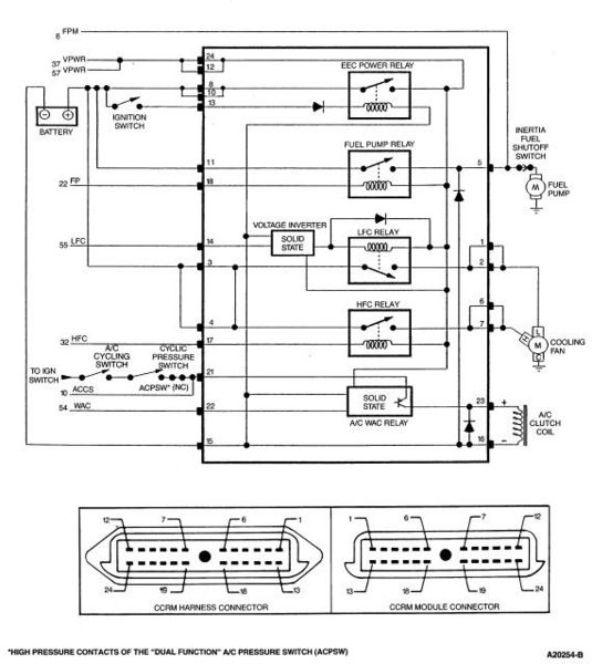
CCRM Diagram
Diagram courtesy of Mustang Fuse & Wiring Diagrams
Power feed: Look for 12 volts at the pink/black wire (power source for fuel pump relay). No voltage or low voltage, bad fuse link, bad wiring, or connections.
Relay: Turn on the key and jumper the ECC test connector as previously described. Look for 12 volts at the dark green\yellow wire (relay controlled power for the fuel pump). No voltage there means that the relay has failed, or there is a broken wire in the relay control circuit.
Inertia switch: Check the brown/pink wire, it should have 12 volts. No 12 volts there, either the inertia switch is open or has no power to it. Check both sides of the inertia switch: there should be power on the dark green\yellow (inertia switch input) and brown/pink wire (inertia switch output). Power on the dark green\yellow wire and not on the brown/pink wire means the inertia switch is open. Press on the red plunger to reset it to the closed position. Sometimes the inertia switch will be intermittent or will not pass full power. Be sure that there is 12 volts on both sides of the switch with the pump running and that the voltage drop measured across the switch is less than .75 volts.
Pump wiring: Anytime the ignition switch is in the Run position and the test point is jumpered to ground, there should be at least 12 volts present on the black/pink wire. With power off, check the pump ground: you should see less than 1 ohm between the black wire and chassis ground.
Make sure that the power is off the circuit before making any resistance checks.
If the circuit is powered up, your resistance measurements will be inaccurate.
Fuel tank wiring connector
Control circuits:
Relay: The red wire for the fuel pump relay coil gets its power feed from the ECC relay. No 12 volts here, and the ECC relay has failed or there is bad wiring or bad connections coming from it. The ECC relay is located on top of the computer, which is under the passenger’s side kick panel. It is not easy to get to, you must have small hands or pull the passenger side dash speaker out to access it.
Relay: The light blue/orange wire provides a ground path for the relay power. With the test connector jumpered according to the previous instructions, there should be less than .75 volts. Use a test lamp with one side connected to battery power and the other side to the light blue/orange wire on the fuel pump relay. The test light should glow brightly. No glow and you have a broken wire or bad connection between the test connector and the relay. To test the wiring from the computer, remove the passenger side kick panel and disconnect the computer connector. It has a 10 MM bolt that holds it in place. Remove the test jumper from the ECC test connector. With the test lamp connected to power, jumper pin 22 to ground and the test lamp should glow. No glow and the wiring between the computer and the fuel pump relay is bad.
Computer: If you got this far and everything else checked out good, the computer is suspect .Remove the test jumper from the ECC test connector located under the hood . Remove the plastic cover over the computer wiring, but leave the computer wiring connector plugged into the computer. With the ignition switch in the run position, connect a test lamp to the battery and back probe pin 22, the light blue/orange wire with it. The lamp should glow brightly. No glow and the computer has died a sad death.

If you used a voltmeter instead of a test lamp, you should see less than 1 volt.
See the following website for some help from Tmoss (diagram designer) & Stang&2Birds (website host) for help on 88-95 wiring
Mustang FAQ - Wiring & Engine Info Everyone should bookmark this site.
Voltage drop testing of connections and grounds.
Use a Digital Volt Meter (DVM) to measure the voltage drop across a connection or wire. Adding length to the test leads may be required, and does not affect the accuracy of the test. Use 16-18 gauge wire for the test leads if you have to lengthen them.
Voltage drop increases with the increase of current in a circuit and it also increases with heat. Put a maximum current load on a bad wire or connection and it gets hot and drops more voltage across the wire or connection. As it heats up, resistance increases which makes more heat. Round and round you go in a vicious circle until something catches fire or fails.
Voltage drop testing must be done while the usual load is on the circuit. If it is a starter, it has to be tested while cranking the starter. If it is lights, A/C or fan, they must be turned on high while testing. Fail to do this and you will not get accurate results
1.) Most grounds use the negative battery post as their starting point. Keep this in mind when checking grounds.
2.) The voltage will be small if the ground is good: less voltage drop = better connection.
3.) Be sure that the power to the circuit is on, and the circuit is being used in its normal manner. For instance, if it is a light circuit, the lights on that circuit should be powered on.
4.) To measure grounds, place one DVM lead on the battery negative post and the other on the wire or connector that goes to ground.
5.) 5.) Voltage drops should not exceed the following:
200 mV Wire or cable
300 mV Switch
100 mV Ground
0 mV to <50 mV Sensor Connections (sensors are low voltage devices and small drops can have a large effect on the devices dependent on sensor accuracy)
0.0V Connections
A voltage drop lower that spec is always acceptable.
6.)
See http://assets.fluke.com/appnotes/automotive/beatbook.pdf for help for help troubleshooting voltage drops across connections and components. .