
Hey guys it's been awhile did a few things to my old ruststang put a new fuel pump in and fix a few minor issue with the heat, air, and lights. Any way having a problem with a back fire when I'm running 80 and slowing down it backfires and loses all power pretty much then surges and I get power back. Like I said I replaced the fuel pump it's got 2 month old auto lite 24s, brand new wires and a brand new msd cap and rotor. Also had to redo my header gaskets and number 4 exhaust valve is dumping oil enough for the header and port on the head to be cover in dried oil.
You are using an out of date browser. It may not display this or other websites correctly.
You should upgrade or use an alternative browser.
You should upgrade or use an alternative browser.
Back Fire Problem
- Thread starter BrandonG08
- Start date
Dump the codes: Codes may be present even if the Check Engine Light (CEL) isn't on.
Dumping the computer diagnostic codes on 86-95 Mustangs
Revised 26-July-2011. Added need to make sure the clutch is pressed when dumping codes.
Codes may be present even if the check engine light hasn’t come on, so be sure to check for them.
Here's the way to dump the computer codes with only a jumper wire or paper clip and the check engine light, or test light or voltmeter. I’ve used it for years, and it works great. You watch the flashing test lamp or Check Engine Light and count the flashes.
Post the codes you get and I will post 86-93 model 5.0 Mustang specific code definitions and fixes. I do not have a complete listing for 94-95 model 5.0 Mustangs at this time.
Be sure to turn off the A/C, and put the transmission in neutral when dumping the codes. On a manual transmission car, be sure to press the clutch to the floor.
Fail to do this and you will generate a code 67 and not be able to dump the Engine Running codes.


If your car is an 86-88 stang, you'll have to use the test lamp or voltmeter method. There is no functional check engine light on the 86-88's except possibly the Cali Mass Air cars.

The STI has a gray connector shell and a white/red wire. It comes from the same bundle of wires as the self test connector.
89 through 95 cars have a working Check Engine light. Watch it instead of using a test lamp.

The STI has a gray connector shell and a white/red wire. It comes from the same bundle of wires as the self test connector.
WARNING!!! There is a single dark brown connector with a black/orange wire. It is the 12 volt power to the under the hood light. Do not jumper it to the computer test connector. If you do, you will damage the computer.
What to expect:
You should get a code 11 (two single flashes in succession). This says that the computer's internal workings are OK, and that the wiring to put the computer into diagnostic mode is good. No code 11 and you have some wiring problems. This is crucial: the same wire that provides the ground to dump the codes provides signal ground for the TPS, EGR, ACT and Map/Baro sensors. If it fails, you will have poor performance, economy and driveablity problems
Some codes have different answers if the engine is running from the answers that it has when the engine isn't running. It helps a lot to know if you had the engine running when you ran the test.
Dumping the Engine Running codes: The procedure is the same, you start the engine with the test jumper in place. Be sure the A/C is off, and clutch (if present) is pressed to the floor, and the transmission is in neutral. You'll get an 11, then a 4 and the engine will speed up to do the EGR test. After the engine speed decreases back to idle, it will dump the engine running codes.
Trouble codes are either 2 digit or 3 digit, there are no cars that use both 2 digit codes and 3 digit codes.
Your 86-88 5.0 won't have a working Check Engine Light, so you'll need a test light.
See AutoZone Part Number: 25886 , $10

Alternate methods:
For those who are intimidated by all the wires & connections, see Actron® for what a typical hand scanner looks like. Normal retail price is about $30 or so at AutoZone or Wal-Mart.
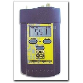
Or for a nicer scanner see Equus Digital Ford Code Reader (3145) Equus - Digital Ford Code Reader 3145.
It has a 3 digit LCD display so that you don’t have to count flashes or beeps.. Cost is $22-$36.
Dumping the computer diagnostic codes on 86-95 Mustangs
Revised 26-July-2011. Added need to make sure the clutch is pressed when dumping codes.
Codes may be present even if the check engine light hasn’t come on, so be sure to check for them.
Here's the way to dump the computer codes with only a jumper wire or paper clip and the check engine light, or test light or voltmeter. I’ve used it for years, and it works great. You watch the flashing test lamp or Check Engine Light and count the flashes.
Post the codes you get and I will post 86-93 model 5.0 Mustang specific code definitions and fixes. I do not have a complete listing for 94-95 model 5.0 Mustangs at this time.
Be sure to turn off the A/C, and put the transmission in neutral when dumping the codes. On a manual transmission car, be sure to press the clutch to the floor.
Fail to do this and you will generate a code 67 and not be able to dump the Engine Running codes.
If your car is an 86-88 stang, you'll have to use the test lamp or voltmeter method. There is no functional check engine light on the 86-88's except possibly the Cali Mass Air cars.
The STI has a gray connector shell and a white/red wire. It comes from the same bundle of wires as the self test connector.
89 through 95 cars have a working Check Engine light. Watch it instead of using a test lamp.
The STI has a gray connector shell and a white/red wire. It comes from the same bundle of wires as the self test connector.
WARNING!!! There is a single dark brown connector with a black/orange wire. It is the 12 volt power to the under the hood light. Do not jumper it to the computer test connector. If you do, you will damage the computer.
What to expect:
You should get a code 11 (two single flashes in succession). This says that the computer's internal workings are OK, and that the wiring to put the computer into diagnostic mode is good. No code 11 and you have some wiring problems. This is crucial: the same wire that provides the ground to dump the codes provides signal ground for the TPS, EGR, ACT and Map/Baro sensors. If it fails, you will have poor performance, economy and driveablity problems
Some codes have different answers if the engine is running from the answers that it has when the engine isn't running. It helps a lot to know if you had the engine running when you ran the test.
Dumping the Engine Running codes: The procedure is the same, you start the engine with the test jumper in place. Be sure the A/C is off, and clutch (if present) is pressed to the floor, and the transmission is in neutral. You'll get an 11, then a 4 and the engine will speed up to do the EGR test. After the engine speed decreases back to idle, it will dump the engine running codes.
Trouble codes are either 2 digit or 3 digit, there are no cars that use both 2 digit codes and 3 digit codes.
Your 86-88 5.0 won't have a working Check Engine Light, so you'll need a test light.
See AutoZone Part Number: 25886 , $10
Alternate methods:
For those who are intimidated by all the wires & connections, see Actron® for what a typical hand scanner looks like. Normal retail price is about $30 or so at AutoZone or Wal-Mart.
Or for a nicer scanner see Equus Digital Ford Code Reader (3145) Equus - Digital Ford Code Reader 3145.
It has a 3 digit LCD display so that you don’t have to count flashes or beeps.. Cost is $22-$36.
You have a lot of serious codes which will definitely have a negative effect on the way the car runs., Judging by the number of codes and the sensors they point to, you have a signal ground problem.I got code 22, 23, 34, 51, 53, 54, 66
Troubleshooting loss of signal ground on pin 46 for 86-90 model 5.0 Mustangs.
Revised 04-Mar-2012 to add 10 pin salt & pepper location and diagrams
A fault in the TPS circuit where the voltage goes above. 4.3 volts at idle can shut off the injectors.
TPS adjustment:
Wire colors & functions:
Orange/white = 5 volt VREF from the computer
Dark Green/lt green = TPS output to computer
Black/white = Signal ground from computer
Always use the Dark green/lt green & Black/white wires to set the TPS base voltage.
Do the test with the ignition switch in the Run position without the engine running.
Use the Orange/white & Black white wires to verify the TPS has the correct 5 volts
source from the computer.
Adjusting the TPS fails to resolve the problem:
If the adjustment does not work to get the voltage below 1 volt, you probably have a bad signal ground. The black/white wire is computer pin 46 and is signal ground for many things. If it burns up inside the computer you get multiple faults and cannot pull codes..
Disconnect the positive battery cable to insure correct results when measuring the resistance of grounds. The small voltage drop that is often in a circuit can cause erroneous readings. Since the computer and several other things still draw current even with the ignition switch in the Off position, this is a necessary step.
Check the black/white wire resistance. Connect one ohmmeter lead to the black/white wire on the TPS and one lead to the negative post on the battery. You should see less than 1.5 ohm, more than that indicates a problem. Always take resistance measurements with the circuit powered off.
Clean the 10 pin salt & pepper shaker connectors.
Diagram courtesy of Tmoss & Stang&2birds
How it is supposed to work:
The black/white wire (computer pin 46) is signal ground for the computer. It provides a dedicated ground for the EGR, Baro, ACT, ECT, & TPS sensors as well as the ground to put the computer into self test mode. Since it is a dedicated ground, it passes through the computer on its way to the computer main power ground that terminates at the battery pigtail ground. It should read less than 1.5 ohms when measured from anyplace on the engine harness with the battery pigtail ground as the other reference point for the ohmmeter probe. What sometimes happens is that it gets jumpered to power which either burns up the wiring or burns the trace off the pc board inside the computer. That trace connects pins 46 to pins 40 & 60, which are power ground for the computer.
See Computer issue? | Mustang Forums at StangNet for Joel5.0’s fix for the computer internal signal ground.
How to test the wiring :
Disconnect the positive battery cable to insure correct results when measuring the resistance of grounds. The small voltage drop that often in a circuit can cause erroneous readings. Since the computer and several other things still draw current even with the ignition switch in the Off position, this is a necessary step.
With the power off, measure the resistance between the computer test ground (black/white wire) on the self test connector and battery ground. You should see less than 1.5 ohms.
If that check fails, remove the passenger side kick panel and disconnect the computer connector. There is a 10 MM bolt that holds it in place. Measure the resistance between the black/white wire and pin 46: it should be less than 1.5 ohms. More that 1.5 ohms is a wiring problem. If it reads 1.5 ohms or less, then the computer is suspect. On the computer, measure the resistance between pin 46 and pins 40 & 60: it should be less than 1.5 ohms. More that that and the computer’s internal ground has failed, and the computer needs to be replaced.
Measure the resistance between the black/white wire on each of the following sensors: TPS, ECT, ACT and EGR. If you find one that is greater than 1.5 ohms, measure between that sensor and pin #1 of the white 10 pin connectors. Pin #1 is the center pin and is labeled sig-rtrn on the diagram
See the graphic for the 10 pin connector circuit layout.
The injector power pin is the VPWR pin in the black 10 pin connector.
MAP/BARO sensor operation and code 22
Revised 14-Nov-2014 to add wire colors for frequency & voltage testing and engine sensor wiring diagrams.
On a Speed Density car, the MAP/BARO sensor is connected to the intake manifold and acts to sense the manifold pressure. Lower vacuum inside the intake manifold when combined with more throttle opening measured by the TPS means more airflow through the engine. As airflow increases, fuel flow through the injectors needs to increase to keep the air/fuel ratio where it needs to be. When manifold vacuum increases, the engine is either decelerating or idling, and it needs to reduce the fuel flow through the injectors.
On a Mass Air car, the MAP/BARO sensor vents to open air and actually senses the barometric pressure due to changes in weather and altitude. Its purpose is to set a baseline for the computer to know the barometric pressure. As barometric pressure decreases, it leans out the fuel flow to compensate for less oxygen in the air. When the barometric pressure rises, it increases to add fuel since there is more oxygen in the air. The fuel requirements decrease as altitude increases, since the atmospheric pressure decreases.
Disconnecting the MAP or BARO sensor will set code 22.
Misconnecting the BARO sensor to vacuum on a Mass Air car will cause the computer to lean out the fuel mixture.
Code 22 or 126 MAP (vacuum) or BARO signal out of range. The MAP or BARO sensor is pretty much the same sensor for both Mass Air & Speed Density cars. The main difference is where it is connected. Mass Air cars vent it to the atmosphere, while Speed Density cars connect it to the intake manifold vacuum. Its purpose is to help set a baseline for the air/fuel mixture by sensing changes in barometric pressure. The MAP or BAP sensor puts out a 5 volt square wave that changes frequency with variations in atmospheric pressure. The base is 154 HZ at 29.92" of mercury - dry sunny day at sea level, about 68-72 degrees. You need an oscilloscope or frequency meter to measure it. There a very few DVM’s with a price tag under $40 that will measure frequency, but there are some out there.
Map sensor wiring:
black/white - ground
orange/white or +5 volts power
white/red signal out.
Measure the +5 volt supply using the orange/white and black/white wires
Measure the signal using the black/white and white/red wires.
The MAP/BARO sensor is mounted on the firewall behind the upper manifold on 86-93 Mustangs.
Baro or MAP test using a real frequency meter - run the test key on, engine off. The noise from the ignition system will likely upset the frequency meter. I used a 10 x oscilloscope probe connected from the frequency meter to the MAP/BAP to reduce the jitter in the meter's readout. And oscilloscope is very useful if you have access to one or know of someone who does. With an oscilloscope, you can see the waveform and amplitude.
If it is defective, your air/fuel ratio will be off and the car’s performance & emissions will suffer
Some basic checks you can make to be sure that the sensor is getting power & ground:
Note that all resistance tests must be done with power off. Measuring resistance with a circuit powered on will give false readings and possibly damage the meter.
Check the resistance between the black/white wire on the MAP/BARO sensor and then the black/white wire on the EGR and the same wire on the TPS. It should be less than 1 ohm. Next check the resistance between the black/white wire and the negative battery cable. It should be less than 1.5 ohm.
The following power on check requires you to turn the ignition switch to the Run position.
Use a DVM to check for 5 volts on the orange/white wire. If it is missing, look for +5 volts at the orange/white wire on the TPS or EGR sensors. Use the black/white wire for the ground for the DVM.
Diagrams courtesy of Tmoss & Stang&2birds
Complete computer, actuator & sensor wiring diagram for 88-91 Mass Air Mustangs

Complete computer, actuator & sensor wiring diagram for 91-93 Mass Air Mustangs

Code 23 - Throttle sensor out of range or throttle set too high - TPS needs to be reset to below 1.2 volts at idle. Keep in mind that when you turn the idle screw to set the idle speed, you change the TPS setting.
You'll need a Digital Voltmeter (DVM) to do the job.
Wire colors & functions:
Orange/white = 5 volt VREF from the computer
Dark Green/lt green = TPS output to computer
Black/white = Signal ground from computer
Always use the Dark Green/lt green & Black/white wires to set the TPS base voltage.
Do the test with the ignition switch in the Run position without the engine running.
Use the Orange/white & Black white wires to verify the TPS has the correct 5 volts source from the computer.
When you installed the sensor make sure you place it on the peg right and then tighten it down properly. Loosen the back screw a tiny bit so the sensor can pivot and loosen the front screw enough so you can move it just a little in very small increments. I wouldn’t try to adjust it using marks. Set it at .6.v-.9 v.
1. Always adjust the TPS and Idle with the engine at operating temp. Dive it around for a bit if you can and get it nice and warm.
2. When you probe the leads of the TPS, do not use an engine ground, put the ground probe into the lead of the TPS. You should be connecting both meter probes to the TPS and not one to the TPS and the other to ground.
If setting the TPS doesn’t fix the problem, then you may have wiring problems.
With the power off, measure the resistance between the black/white wire and battery ground. You should see less than 2 ohms. Check the same black /white wire on the TPS and MAP/Baro sensor. More than 1 ohm there and the wire is probably broken in the harness between the engine and the computer. The 10 pin connectors pass the black/white wire back to the computer, and can cause problems.
See the following website for some help from Tmoss (diagram designer) & Stang&2Birds (website host)
http://www.veryuseful.com/mustang/tech/engine/images/88-91eecPinout.gif
Code 34 Or 334 - EGR voltage above closed limit –
Revised 26-Sep-2011 to add EGR cleaning and movement test for pintle when vacuum is applied to diaphragm
Failed sensor, carbon between EGR pintle valve and seat holding the valve off its seat. Remove the EGR valve and clean it with carbon remover. Prior to re-installing see if you can blow air through the flange side of the EGR by mouth. If it leaks, there is carbon stuck on the pintle valve seat clean or, replace the EGR valve ($85-$95).
Recommended procedure for cleaning the EGR:
Conventional cleaning methods like throttle body cleaner aren’t very effective. The best method is a soak type cleaner used for carburetors. If you are into fixing motorcycles, jet skis, snowmobiles or anything else with a small carburetor, you probably have used the one gallon soak cleaners like Gunk or Berryman. One of the two should be available at your local auto parts store for $22-$29. There is a basket to set the parts in while they are soaking. Soak the metal body in the carb cleaner overnight. Don’t immerse the diaphragm side, since the carb cleaner may damage the diaphragm. If you get any of the carb cleaner on the diaphragm, rinse it off with water immediately. Rinse the part off with water and blow it dry with compressed air. Once it has dried, try blowing through the either hole and it should block the air flow. Do not put parts with water on them or in them in the carb cleaner. If you do, it will weaken the carb cleaner and it won’t clean as effectively.
Gunk Dip type carb & parts soaker:

If you have a handy vacuum source, apply it to the diaphragm and watch to see if the pintle moves freely. Try blowing air through either side and make sure it flows when the pintle retracts and blocks when the pintle is seated. If it does not, replace the EGR.
If the blow by test passes, and you have replaced the sensor, then you have electrical ground problems. Check the resistance between the black/white wire on the MAP/BARO sensor and then the black/white wire on the EGR and the same wire on the TPS. It should be less than 1.5 ohm. Next check the resistance between the black/white wire and the negative battery post. It should be less than 1.5 ohm.
Note that all resistance tests must be done with power off. Measuring resistance with a circuit powered on will give false readings and possibly damage the meter.
Let’s put on our Inspector Gadget propeller head beanies and think about how this works:
The EGR sensor is a variable resistor with ground on one leg and Vref (5 volts) on the other. Its’ resistance ranges from 4000 to 5500 Ohms measured between Vref & ground, depending on the sensor. The center connection of the variable resistor is the slider that moves in response to the amount of vacuum applied. The slider has some minimum value of resistance greater than 100 ohms so that the computer always sees a voltage present at its’ input. If the value was 0 ohms, there would be no voltage output. Then the computer would not be able to distinguish between a properly functioning sensor and one that had a broken wire or bad connection. The EGR I have in hand reads 700 Ohms between the slider (EPV) and ground (SIG RTN) at rest with no vacuum applied. The EGR valve or sensor may cause the voltage to be above closed limits due to the manufacturing tolerances that cause the EGR sensor to rest at a higher position than it should.
The following sensors are connected to the white 10 pin connector (salt & pepper engine harness connectors)
This will affect idle quality by diluting the intake air charge
Code 51 Engine Coolant Temperature (ECT) sensor signal is/was too high -
Possible bad ECT sensor, or wiring. Possible missing signal ground –
black/wire wire broken or bad connection. With the power off, measure the
resistance between the black/white wire and battery ground. You should see
less than 1 ohm. Check the same black /white wire on the TPS and MAP
sensor. More than 1 ohm there and the wire is probably broken in the harness
between the engine and the computer. The 10 pin connectors pass the
black/white wire back to the computer, and can cause problems.
The ECT sensor is not the same as the temp sender for the temp gauge. It is located in the front part of the tubing that feeds coolant to the heater. It has two wires connected to it.
Pin 7 on the computer - ECT signal in. at 176 degrees F it should be .80 volts
Voltages may be measured across the ECT by probing the connector from the rear.
Use care in doing it so that you don't damage the wiring or connector.
50 degrees F = 3.52 v
68 degrees F = 3.02 v
86 degrees F = 2.62 v
104 degrees F = 2.16 v
122 degrees F = 1.72 v
140 degrees F = 1.35 v
158 degrees F = 1.04 v
176 degrees F = .80 v
194 degrees F = .61
212 degrees F = .47 v
230 degrees F = .36 v
248 degrees F = .28 v
Ohms measures at the computer with the computer disconnected, or at the sensor with the sensor disconnected.
50 degrees F = 58.75 K ohms
68 degrees F = 37.30 K ohms
86 degrees F = 27.27 K ohms
104 degrees F = 16.15 K ohms
122 degrees F = 10.97 K ohms
140 degrees F = 7.60 K ohms
158 degrees F = 5.37 K ohms
176 degrees F = 3.84 K ohms
194 degrees F = 2.80 K ohms
212 degrees F = 2.07 K ohms
230 degrees F = 1.55 K ohms
248 degrees F = 1.18 k ohms
Diagram courtesy of Tmoss & Stang&2birds
See the following website for some help from Tmoss (diagram designer) & Stang&2Birds (website host) for help on 88-95
Code 53 - Throttle Position sensor too high – TPS – TPS out of adjustment, bad connections, missing signal ground, bad sensor.
Wire colors & functions:
Orange/white = 5 volt VREF from the computer
Dark Green/lt green = TPS output to computer
Black/white = Signal ground from computer
Always use the Dark green/lt green & Black/white wires to set the TPS base voltage.
Do the test with the ignition switch in the Run position without the engine running.
Use the Orange/white & Black white wires to verify the TPS has the correct 5 volts source from the computer.
Setting the TPS: you'll need a good Digital Voltmeter (DVM) to do the job. Set the TPS voltage at .5- 1.1 range. Because of the variables involved with the tolerances of both computer and DVM, I would shoot for somewhere between .6 and 1.0 volts. Unless you have a Fluke or other high grade DVM, the second digit past the decimal point on cheap DVM’s is probably fantasy. Since the computer zeros out the TPS voltage every time it powers up, playing with the settings isn't an effective aid to performance or drivability. The main purpose of checking the TPS is to make sure it isn't way out of range and causing problems.
The Orange/White wire is the VREF 5 volts from the computer. You use the Dark Green/Lt green wire (TPS signal) and the Black/White wire (TPS ground) to set the TPS. Use a pair of safety pins to probe the TPS connector from the rear of the connector. You may find it a little difficult to make a good connection, but keep trying. Put the safety pins in the Dark Green/Lt green wire and Black/White wire. Make sure the ignition switch is in the Run position but the engine isn't running.
Here’s a TPS tip I got from NoGo50
When you installed the sensor make sure you place it on the peg right and then tighten it down properly. Loosen the back screw a tiny bit so the sensor can pivot and loosen the front screw enough so you can move it just a little in very small increments. I wouldn’t try to adjust it using marks.
(copied from MustangMax, Glendale AZ)
A.) Always adjust the TPS and Idle with the engine at operating temp. Dive it around for a bit if you can and get it nice and warm.
B.) When you probe the leads of the TPS, do not use an engine ground, put the ground probe into the lead of the TPS. You should be connecting both meter probes to the TPS and not one to the TPS and the other to ground.
C.) Always reset the computer whenever you adjust the TPS or clean/change any sensors. I just pull the battery lead for 10 minutes.
D.) The key is to adjust the TPS voltage and reset the computer whenever the idle screw is changed.
The TPS is a variable resistor, must like the volume control knob on a cheap radio. We have all heard them crackle and pop when the volume is adjusted. The TPS sensor has the same problem: wear on the resistor element makes places that create electrical noise. This electrical noise confuses the computer, because it expects to see a smooth increase or decrease as the throttle is opened or closed.
TPS testing: most of the time a failed TPS will set code 23 or 63, but not always. Use either an analog meter or a DVM with an analog bar graph and connect the leads as instructed above. Turn the ignition switch to the Run position, but do not start the engine. Note the voltage with the throttle closed. Slowly open the throttle and watch the voltage increase smoothly, slowly close the throttle and watch the voltage decrease smoothly. If the voltage jumps around and isn’t smooth, the TPS has some worn places in the resistor element. When the throttle is closed, make sure that the voltage is the same as what it was when you started. If it varies more than 10%, the TPS is suspect of being worn in the idle range of its travel.
Adjusting the TPS fails to resolve the problem:
Check the black/white wire resistance. Connect one ohmmeter lead to the black/white wire on the TPS and one lead to the negative post on the battery. You should see less than 1.5 ohm, more than that indicates a problem. Always take resistance measurements with the circuit powered off.
Clean the 10 pin salt & pepper shaker connectors.
Code 54 – ACT sensor out of range. Broken or damaged wiring, bad ACT sensor. Note that that if the outside air temp is below 50 degrees F that the test for the ACT can be in error.
Check the resistance of the black/white wire to battery ground. If it is less than 2 ohms, it is good. If it is more than 2 ohms, the black/white wire has bad connections or a broken wire. Always take resistance measurements with the circuit powered off.
See the graphic for the 10 pin connector circuit layout.
Then check the resistance of the ACT sender located in the #5 intake runner on most 5.0 stangs.
ACT & ECT test data:
The ACT & ECT have the same thermistor, so the table values are the same
Pin 7 on the computer - ECT signal in. at 176 degrees F it should be .80 volts
Pin 25 on the computer - ACT signal in. at 50 degrees F it should be 3.5 volts. It is a good number if the ACT is mounted in the inlet airbox. If it is mounted in the lower intake manifold, the voltage readings will be lower because of the heat transfer. Here's the table :
68 degrees F = 3.02 v
86 degrees F = 2.62 v
104 degrees F = 2.16 v
122 degrees F = 1.72 v
140 degrees F = 1.35 v
158 degrees F = 1.04 v
176 degrees F = .80 v
194 degrees F = .61
Ohms measures at the computer with the computer disconnected, or at the sensor with the sensor disconnected.
50 degrees F = 58.75 K ohms
68 degrees F = 37.30 K ohms
86 degrees F = 27.27 K ohms
104 degrees F = 16.15 K ohms
122 degrees F = 10.97 K ohms
140 degrees F = 7.60 K ohms
158 degrees F = 5.37 K ohms
176 degrees F = 3.84 K ohms
194 degrees F = 2.80 K ohms
Code 66 or 157 MAF below minimum test voltage.
Revised 10-Feb-2014 to add 95-95 Mustang code 157 and 94-95 ECC diagram
Insufficient or no voltage from MAF. Dirty MAF element, bad MAF, bad MAF wiring, missing power to MAF. Check for missing +12 volts on this circuit. Check the two links for a wiring diagram to help you find the red wire for computer power relay switched +12 volts. Check for 12 volts between the red and black wires on the MAF heater (usually pins A & B). while the connector is plugged into the MAF. This may require the use of a couple of safety pins to probe the MAF connector from the back side of it.
Computer connector for 88-93 5.0 Mustangs
Diagrams courtesy of Tmoss and Stang&2Birds
ECC Diagram for 88-90 5.0 Mustangs
ECC Diagram for 91-93 5.0 Mustangs
94-95 Diagram for 94-95 5.0 Mustangs

There are three parts in a MAF: the heater, the sensor element and the amplifier. The heater heats the MAF sensor element causing the resistance to increase. The amplifier buffers the MAF output signal and has a resistor that is laser trimmed to provide an output range compatible with the computer's load tables. Changes in RPM causes the airflow to increase or decrease, changing the voltage output.. The increase of air across the MAF sensor element causes it to cool, allowing more voltage to pass and telling the computer to increase the fuel flow. A decrease in airflow causes the MAF sensor element to get warmer, decreasing the voltage and reducing the fuel flow.
The MAF element is secured by 2 screws & has 1 wiring connector. To clean the element, remove it from the MAF housing and spray it down with electronic parts cleaner or non-inflammable brake parts cleaner (same stuff in a bigger can and cheaper too).
89-90 Model cars: Measure the MAF output at pins C & D on the MAF connector (dark blue/orange and tan/light blue) or at pins 50 & 9 on the computer. Be sure to measure the sensor output by measuring across the pins and not between the pins and ground.
91-95 Model cars: Measure the MAF output at pins C & D on the MAF connector light blue/red and tan/light blue) or at pins 50 & 9 on the computer. Be sure to measure the sensor output by measuring across the pins and not between the pins and ground.
At idle = approximately .6 volt
20 MPH = approximately 1.10 volt
40 MPH = approximately 1.70 volt
60 MPH = approximately 2.10 volt
Check the resistance of the MAF signal wiring. Pin D on the MAF and pin 50 on the computer (dark blue/orange wire) should be less than 2 ohms. Pin C on the MAF and pin 9 on the computer (tan/light blue wire) should be less than 2 ohms.
There should be a minimum of 10K ohms between either pin C or D on the MAF wiring connector and pins A or B. Make your measurement with the MAF disconnected from the wiring harness.
Actually MAF pins C & D float with reference to ground. The signal output of the MAF is a differential amplifier setup. Pins C & D both carry the output signal, but one pin's output is inverted from the other. The difference in signal between C & D is what the computer's input circuit is looking for. The difference in the two outputs helps cancel out electrical noise generated by the ignition system and other components. Since the noise will be of the same polarity, wave shape and magnitude, the differential input of the computer electronically subtracts it from the signal. Then it passes the signal on to an Analog to Digital converter section inside the computer's CPU chip.
See the following website for some help from Tmoss (diagram designer) & Stang&2Birds (website host) for help on 88-95 wiring Mustang FAQ - Wiring & Engine Info
Ignition switch wiring
http://www.veryuseful.com/mustang/tech/engine/images/IgnitionSwitchWiring.gif
Fuel pump, alternator, ignition & A/C wiring
http://www.veryuseful.com/mustang/tech/engine/images/fuel-alt-links-ign-ac.gif
Computer,. actuator & sensor wiring
http://www.veryuseful.com/mustang/tech/engine/images/88-91_5.0_EEC_Wiring_Diagram.gif
Fuse panel layout
http://www.veryuseful.com/mustang/tech/engine/images/MustangFuseBox.gif
Vacuum routing
http://www.veryuseful.com/mustang/tech/engine/images/mustangFoxFordVacuumDiagram.jpg[/b]
Attachments

Last edited:
Short the meter probe tips together and see what you get.I'm getting 2 ohms everywhere
It read ol for overload I use my fluke 87 I put another computer in it now it's misfiring constant with no check engine light
Fix the codes, disconnect the battery for 5 minutes with the headlights turned on. Turn the headlights off, and reconnect the battery. Then drive the car for a 15-20 minutes at highway speed for the computer to learn the sensor output from the sensors you replaced/repaired. Drive for a day or two and dump the codes again.
Code 18 - SPOUT out or wiring fault - look for short to ground in SPOUT wiring going
back to the computer. Possible bad TFI or defective 22 K resistor in the IDM wiring
Use a timing light to check the timing: remove the SPOUT and observe that the timing retards at least 4 degrees. Put the SPOUT back in place and observe that the spark advances at least 4 degrees.
This code can disable spark advance and reduce power and fuel economy.
Remove the passenger side kick panel and disconnect the computer connector.
There is a 10 MM bolt that holds it in place.
Disconnect the TFI module connector from the TFI and the measure the resistance between the yellow/lt green wire and ground.
You should see greater than 100 K (100000) ohms.
Check the resistance from Pin 4 on the computer connector (dark green/yellow) and the dark green/yellow wire on the TFI connector. You should see 20-24 K Ohms (20,000-24,0000 ohms).
Resistor location: A big thanks to liljoe07 for this information:
Next measure the resistance between the yellow/lt green wire on the TFI module connector and Pin 36 on the computer connector. With the SPOUT plug in place, you should see less than 2 ohms.
The following is a view from the computer side of the computer connector.
This diagram is the wire side of the computer connector.

Diagram courtesy of Tmoss & Stang&2birds
Code 34 Or 334 - EGR voltage above closed limit –
Revised 26-Sep-2011 to add EGR cleaning and movement test for pintle when vacuum is applied to diaphragm
Failed sensor, carbon between EGR pintle valve and seat holding the valve off its seat. Remove the EGR valve and clean it with carbon remover. Prior to re-installing see if you can blow air through the flange side of the EGR by mouth. If it leaks, there is carbon stuck on the pintle valve seat clean or, replace the EGR valve ($85-$95).
Recommended procedure for cleaning the EGR:
Conventional cleaning methods like throttle body cleaner aren’t very effective. The best method is a soak type cleaner used for carburetors. If you are into fixing motorcycles, jet skis, snowmobiles or anything else with a small carburetor, you probably have used the one gallon soak cleaners like Gunk or Berryman. One of the two should be available at your local auto parts store for $22-$29. There is a basket to set the parts in while they are soaking. Soak the metal body in the carb cleaner overnight. Don’t immerse the diaphragm side, since the carb cleaner may damage the diaphragm. If you get any of the carb cleaner on the diaphragm, rinse it off with water immediately. Rinse the part off with water and blow it dry with compressed air. Once it has dried, try blowing through the either hole and it should block the air flow. Do not put parts with water on them or in them in the carb cleaner. If you do, it will weaken the carb cleaner and it won’t clean as effectively.
Gunk Dip type carb & parts soaker:
If you have a handy vacuum source, apply it to the diaphragm and watch to see if the pintle moves freely. Try blowing air through either side and make sure it flows when the pintle retracts and blocks when the pintle is seated. If it does not, replace the EGR.
If the blow by test passes, and you have replaced the sensor, then you have electrical ground problems. Check the resistance between the black/white wire on the MAP/BARO sensor and then the black/white wire on the EGR and the same wire on the TPS. It should be less than 1.5 ohm. Next check the resistance between the black/white wire and the negative battery post. It should be less than 1.5 ohm.
Note that all resistance tests must be done with power off. Measuring resistance with a circuit powered on will give false readings and possibly damage the meter.
Let’s put on our Inspector Gadget propeller head beanies and think about how this works:
The EGR sensor is a variable resistor with ground on one leg and Vref (5 volts) on the other. Its’ resistance ranges from 4000 to 5500 Ohms measured between Vref & ground, depending on the sensor. The center connection of the variable resistor is the slider that moves in response to the amount of vacuum applied. The slider has some minimum value of resistance greater than 100 ohms so that the computer always sees a voltage present at its’ input. If the value was 0 ohms, there would be no voltage output. Then the computer would not be able to distinguish between a properly functioning sensor and one that had a broken wire or bad connection. The EGR I have in hand reads 700 Ohms between the slider (EPV) and ground (SIG RTN) at rest with no vacuum applied. The EGR valve or sensor may cause the voltage to be above closed limits due to the manufacturing tolerances that cause the EGR sensor to rest at a higher position than it should.
The following sensors are connected to the white 10 pin connector (salt & pepper engine harness connectors)

This will affect idle quality by diluting the intake air charge
Code 41 or 91. Or 43 Three digit code 172 or 176 - O2 sensor indicates system lean. Look for a vacuum leak or failing O2 sensor.
Revised 11-Jan-2015 to add check for fuel pressure out of range
Code 41 is the passenger side sensor, as viewed from the driver's seat.
Code 91 is the driver side sensor, as viewed from the driver's seat.
Code 172 is the passenger side sensor as viewed from the driver's seat.
Code 176 is the driver side sensor, as viewed from the driver's seat.
Code 43 is not side specific according to the Probst Ford Fuel injection book.
The computer sees a lean mixture signal coming from the O2 sensors and tries to compensate by adding more fuel. Many times the end result is an engine that runs pig rich and stinks of unburned fuel.
The following is a Quote from Charles O. Probst, Ford fuel Injection & Electronic Engine control:
"When the mixture is lean, the exhaust gas has oxygen, about the same amount as the ambient air. So the sensor will generate less than 400 Millivolts. Remember lean = less voltage.
When the mixture is rich, there's less oxygen in the exhaust than in the ambient air , so voltage is generated between the two sides of the tip. The voltage is greater than 600 millivolts. Remember rich = more voltage.
Here's a tip: the newer the sensor, the more the voltage changes, swinging from as low as 0.1 volt to as much as 0.9 volt. As an oxygen sensor ages, the voltage changes get smaller and slower - the voltage change lags behind the change in exhaust gas oxygen.
Because the oxygen sensor generates its own voltage, never apply voltage and never measure resistance of the sensor circuit. To measure voltage signals, use an analog voltmeter with a high input impedance, at least 10 megohms. Remember, a digital voltmeter will average a changing voltage." End Quote
Testing the O2 sensors 87-93 5.0 Mustangs
Measuring the O2 sensor voltage at the computer will give you a good idea of how well they are working. You'll have to pull the passenger side kick panel off to gain access to the computer connector. Remove the plastic wiring cover to get to the back side of the wiring. Use a safety pin or paper clip to probe the connections from the rear.
Disconnect the O2 sensor from the harness and use the body side O2 sensor harness as the starting point for testing. Do not measure the resistance of the O2 sensor , you may damage it. Resistance measurements for the O2 sensor harness are made with one meter lead on the O2 sensor harness and the other meter lead on the computer wire or pin for the O2 sensor.
Backside view of the computer wiring connector:
87-90 5.0 Mustangs:
Computer pin 43 Dark blue/Lt green – LH O2 sensor
Computer pin 29 Dark Green/Pink – RH O2 sensor
The computer pins are 29 (L\RH O2 with a dark green/pink wire) and 43 (LH O2 with a dark blue/pink wire). Use the ground next to the computer to ground the voltmeter. The O2 sensor voltage should switch between .2-.9 volt at idle.
91-93 5.0 Mustangs:
Computer pin 43 Red/Black – LH O2 sensor
Computer pin 29 Gray/Lt blue – RH O2 sensor
The computer pins are 29 (LH O2 with a Gray/Lt blue wire) and 43 (RH O2 with a Red/Black wire). Use the ground next to the computer to ground the voltmeter. The O2 sensor voltage should switch between .2-.9 volt at idle.
Testing the O2 sensors 94-95 5.0 Mustangs
Measuring the O2 sensor voltage at the computer will give you a good idea of how well they are working. You'll have to pull the passenger side kick panel off to gain access to the computer connector. Remove the plastic wiring cover to get to the back side of the wiring. Use a safety pin or paper clip to probe the connections from the rear. The computer pins are 29 (LH O2 with a red/black wire) and 27 (RH O2 with a gray/lt blue wire). Use pin 32 (gray/red wire) to ground the voltmeter. The O2 sensor voltage should switch between .2-.9 volt at idle.
Note that all resistance tests must be done with power off. Measuring resistance with a circuit powered on will give false readings and possibly damage the meter. Do not attempt to measure the resistance of the O2 sensors, it may damage them.
Testing the O2 sensor wiring harness
Most of the common multimeters have a resistance scale. Be sure the O2 sensors are disconnected and measure the resistance from the O2 sensor body harness to the pins on the computer. Using the Low Ohms range (usually 200 Ohms) you should see less than 1.5 Ohms.
87-90 5.0 Mustangs:
Computer pin 43 Dark blue/Lt green – LH O2 sensor
Computer pin 29 Dark Green/Pink – RH O2 sensor
Disconnect the connector from the O2 sensor and measure the resistance:
From the Dark blue/Lt green wire in the LH O2 sensor harness and the Dark blue/Lt green wire on the computer pin 43
From the Dark Green/Pink wire on the RH Os sensor harness and the Dark Green/Pink wire on the computer pin 29
91-93 5.0 Mustangs:
Computer pin 43 Red/Black – LH O2 sensor
Computer pin 29 Gray/Lt blue – RH O2 sensor
Disconnect the connector from the O2 sensor and measure the resistance:
From the Red/Black wire in the LH O2 sensor harness and the Red/Black wire on the computer pin 43
From the Dark Green/Pink Gray/Lt blue wire on the RH Os sensor harness and the Gray/Lt blue wire on the computer pin 29
94-95 5.0 Mustangs:
Computer pin 29 Red/Black – LH O2 sensor
Computer pin 27 Gray/Lt blue – RH O2 sensor
From the Red/Black wire in the LH O2 sensor harness and the Red/Black wire on the computer pin 29
From the Dark Green/Pink Gray/Lt blue wire on the RH Os sensor harness and the Gray/Lt blue wire on the computer pin 27
There is a connector between the body harness and the O2 sensor harness. Make sure the connectors are mated together, the contacts and wiring are not damaged and the contacts are clean and not coated with oil.
The O2 sensor ground (orange wire with a ring terminal on it) is in the wiring harness for the fuel injection wiring. I grounded mine to one of the intake manifold bolts
Check the fuel pressure – the fuel pressure is 37-41 PSI with the vacuum disconnected and the engine idling. Fuel pressure out of range can cause the 41 & 91 codes together. It will not cause a single code, only both codes together.
Make sure you have the proper 3 wire O2 sensors. Only the 4 cylinder cars used a 4 wire sensor, which is not compatible with the V8 wiring harness.
Replace the O2 sensors in pairs if replacement is indicated. If one is weak or bad, the other one probably isn't far behind.
Code 41 can also be due to carbon plugging the driver’s side Thermactor air crossover tube on the back of the engine. The tube fills up with carbon and does not pass air to the driver’s side head ports. This puts an excess amount of air in the passenger side exhaust and can set the code 41. Remove the tube and clean it out so that both sides get good airflow: this may be more difficult than it sounds. You need something like a mini rotor-rooter to do the job because of the curves in the tube. Something like the outer spiral jacket of a flexible push-pull cable may be the thing that does the trick.
If you get only code 41 and have changed the sensor, look for vacuum leaks. This is especially true if you are having idle problems. The small plastic tubing is very brittle after many years of the heating it receives. Replace the tubing and check the PVC and the hoses connected to it.
Code 26 - Mass Air Flow out of range – MAF
There are three parts in a MAF: the heater, the sensor element and the amplifier. The heater heats the MAF sensor element causing the resistance to increase. The amplifier buffers the MAF output signal and has a resistor that is laser trimmed to provide an output range compatible with the computer's load tables.
The MAF element is secured by 2 screws & has 1 wiring connector. To clean the element, remove it from the MAF housing and spray it down with electronic parts cleaner or non-inflammable brake parts cleaner (same stuff in a bigger can and cheaper too).
Look for 12 volts across pins A & B.
The MAF output varies with RPM which causes the airflow to increase or decease. The increase of air across the MAF sensor element causes it to cool, allowing more voltage to pass and telling the computer to increase the fuel flow. A decrease in airflow causes the MAF sensor element to get warmer, decreasing the voltage and reducing the fuel flow. Measure the MAF output at pins C & D on the MAF connector (dark blue/orange and tan/light blue) or at pins 50 & 9 on the computer.
At idle = approximately .6 volt
20 MPH = approximately 1.10 volt
40 MPH = approximately 1.70 volt
60 MPH = approximately 2.10 volt
Check the resistance of the MAF signal wiring. Pin D on the MAF and pin 50 on the computer (dark blue/orange wire) should be less than 2 ohms. Pin C on the MAF and pin 9 on the computer (tan/light blue wire) should be less than 2 ohms.
There should be a minimum of 10K ohms between either pin C or D on the MAF and ground.
See the following website for some help from Tmoss (diagram designer) & Stang&2Birds (website host)
http://www.veryuseful.com/mustang/tech/engine/images/fuel-alt-links-ign-ac.gif
http://www.veryuseful.com/mustang/tech/engine/images/88-91eecPinout.gif
Code 12 -Idle Air Bypass motor not controlling idle properly (generally idle too low) - IAB dirty or not working. Clean the electrical contacts with non flammable brake parts cleaner at the same time.
IAC doesn't work: look for +12 volts at the IAC red wire. Then check for continuity between the white/lt blue wire and pin 21 on the computer. The IAC connector contacts will sometimes corrode and make the IAC not work. The red wire on the IAC is always hot with the engine in run mode. The computer provides a ground for the current for the IAC. It switches the ground on and off, making a square wave with a varying duty cycle. A normal square wave would be on for 50% of the time and off for 50% of the time. When the idle speed is low, the duty cycle increases more than 50% to open the IAC more. When the engine speed is high, it decreases the duty cycle to less than 50% to close the IAC. An old-fashioned dwell meter can be used to check the change: I haven’t tried it personally, but it should work. In theory, it should read ½ scale of whatever range you set it on with a 50% duty cycle. An Oscilloscope is even better if you can find someone who has one and will help.

Recommended procedure for cleaning the IAC/IAB:
Conventional cleaning methods like throttle body cleaner aren’t very effective. The best method is a soak type cleaner used for carburetors. If you are into fixing motorcycles, jet skis, snowmobiles or anything else with a small carburetor, you probably have used the one gallon soak cleaners like Gunk or Berryman. One of the two should be available at your local auto parts store for $22-$29. Take the solenoid off the body and set it aside: the carb cleaner will damage some types of plastic parts. Soak the metal body in the carb cleaner overnight. There is a basket to set the parts in while they are soaking. When you finish soaking overnight, twist the stem of the IAB/IAC that sticks out while the blocker valve is seated. This removes any leftover deposits from the blocker valve seat. Rinse the part off with water and blow it dry with compressed air. The IAC/IAB should seal up nicely now. Once it has dried, try blowing through the bottom hole and it should block the air flow. Reassemble and reinstall to check it out.
Gunk Dip type carb & parts soaker:
Setting the base idle speed:
First of all, the idle needs to be adjusted to where the speed is at or below 600 RPM with the IAC disconnected. If you have a wild cam, you may have to raise this figure 100-150 RPM or so. Then the electrical signal through the IAC can vary the airflow through it under computer control. Remember that the IAC can only add air to increase the base idle speed set by the mechanical adjustment. The 600 RPM base idle speed is what you have after the mechanical adjustment. The IAC increases that speed by supplying more air under computer control to raise the RPM’s to 650-725 RPM’s. This figure will increase if you have a wild cam, and may end up between 800-950 RPM
Remember that changing the mechanical idle speed adjustment changes the TPS setting too.
This isn't the method Ford uses, but it does work. Do not attempt to set the idle speed until you have fixed all the codes and are sure that there are no vacuum leaks.
Disconnect the battery negative terminal and turn the headlights on. Leave the battery negative terminal disconnected for 5 minutes or so. Then turn the headlights off and reconnect the battery. This erases the computer settings that may affect idle performance.
Warm the engine up to operating temperature, place the transmission in neutral, and set the parking brake. Turn off lights, A/C, all unnecessary electrical loads. Disconnect the IAC electrical connector. Remove the SPOUT plug. This will lock the ignition timing so that the computer won't change the spark advance, which changes the idle speed. Note the engine RPM: use the mechanical adjustment screw under the throttle body to raise or lower the RPM until you get the 600 RPM mark +/- 25 RPM. A wild cam may make it necessary to increase the 600 RPM figure to 700 RPM or possibly a little more to get a stable idle speed.
Changing the mechanical adjustment changes the TPS, so you will need to set it.
When you are satisfied with the results, turn off the engine, and re-install the SPOUT and reconnect the IAC. The engine should idle with the range of 650-750 RPM without the A/C on or extra electrical loads. A wild cam may make this figure somewhat higher.
An engine that whose idle speed cannot be set at 600 RPM with the IAC disconnected has mechanical problems. Vacuum leaks are the #1 suspect in this case. A vacuum gauge will help pinpoint both vacuum leaks and improperly adjusted valves. A sticking valve or one adjusted too tight will cause low vacuum and a 5"-8" sweep every time the bad cylinder comes up on compression stroke. An extreme cam can make the 600 RPM set point difficult to set. Contact your cam supplier or manufacturer to get information on idle speed and quality
Code 18 - SPOUT out or wiring fault - look for short to ground in SPOUT wiring going
back to the computer. Possible bad TFI or defective 22 K resistor in the IDM wiring
Use a timing light to check the timing: remove the SPOUT and observe that the timing retards at least 4 degrees. Put the SPOUT back in place and observe that the spark advances at least 4 degrees.
This code can disable spark advance and reduce power and fuel economy.
Remove the passenger side kick panel and disconnect the computer connector.
There is a 10 MM bolt that holds it in place.
Disconnect the TFI module connector from the TFI and the measure the resistance between the yellow/lt green wire and ground.
You should see greater than 100 K (100000) ohms.
Check the resistance from Pin 4 on the computer connector (dark green/yellow) and the dark green/yellow wire on the TFI connector. You should see 20-24 K Ohms (20,000-24,0000 ohms).
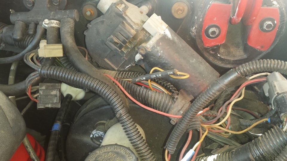
Resistor location: A big thanks to liljoe07 for this information:
Check over by the brake booster. Its not in the harness on the TFI, its on the main part of the harness over by the plugs that connect to the dash harness. About 6" or so from that, going back toward the EEC.
If I remember right, the resistor is covered in a shrink tubing that is sealed to the wires. So, you wont be able see any markings. The shrink tubing is labeled though. It's a 22kohm 1/2 watt resistor.
Here is the location.
Next measure the resistance between the yellow/lt green wire on the TFI module connector and Pin 36 on the computer connector. With the SPOUT plug in place, you should see less than 2 ohms.
The following is a view from the computer side of the computer connector.
This diagram is the wire side of the computer connector.
Diagram courtesy of Tmoss & Stang&2birds
Code 34 Or 334 - EGR voltage above closed limit –
Revised 26-Sep-2011 to add EGR cleaning and movement test for pintle when vacuum is applied to diaphragm
Failed sensor, carbon between EGR pintle valve and seat holding the valve off its seat. Remove the EGR valve and clean it with carbon remover. Prior to re-installing see if you can blow air through the flange side of the EGR by mouth. If it leaks, there is carbon stuck on the pintle valve seat clean or, replace the EGR valve ($85-$95).
Recommended procedure for cleaning the EGR:
Conventional cleaning methods like throttle body cleaner aren’t very effective. The best method is a soak type cleaner used for carburetors. If you are into fixing motorcycles, jet skis, snowmobiles or anything else with a small carburetor, you probably have used the one gallon soak cleaners like Gunk or Berryman. One of the two should be available at your local auto parts store for $22-$29. There is a basket to set the parts in while they are soaking. Soak the metal body in the carb cleaner overnight. Don’t immerse the diaphragm side, since the carb cleaner may damage the diaphragm. If you get any of the carb cleaner on the diaphragm, rinse it off with water immediately. Rinse the part off with water and blow it dry with compressed air. Once it has dried, try blowing through the either hole and it should block the air flow. Do not put parts with water on them or in them in the carb cleaner. If you do, it will weaken the carb cleaner and it won’t clean as effectively.
Gunk Dip type carb & parts soaker:
If you have a handy vacuum source, apply it to the diaphragm and watch to see if the pintle moves freely. Try blowing air through either side and make sure it flows when the pintle retracts and blocks when the pintle is seated. If it does not, replace the EGR.
If the blow by test passes, and you have replaced the sensor, then you have electrical ground problems. Check the resistance between the black/white wire on the MAP/BARO sensor and then the black/white wire on the EGR and the same wire on the TPS. It should be less than 1.5 ohm. Next check the resistance between the black/white wire and the negative battery post. It should be less than 1.5 ohm.
Note that all resistance tests must be done with power off. Measuring resistance with a circuit powered on will give false readings and possibly damage the meter.
Let’s put on our Inspector Gadget propeller head beanies and think about how this works:
The EGR sensor is a variable resistor with ground on one leg and Vref (5 volts) on the other. Its’ resistance ranges from 4000 to 5500 Ohms measured between Vref & ground, depending on the sensor. The center connection of the variable resistor is the slider that moves in response to the amount of vacuum applied. The slider has some minimum value of resistance greater than 100 ohms so that the computer always sees a voltage present at its’ input. If the value was 0 ohms, there would be no voltage output. Then the computer would not be able to distinguish between a properly functioning sensor and one that had a broken wire or bad connection. The EGR I have in hand reads 700 Ohms between the slider (EPV) and ground (SIG RTN) at rest with no vacuum applied. The EGR valve or sensor may cause the voltage to be above closed limits due to the manufacturing tolerances that cause the EGR sensor to rest at a higher position than it should.
The following sensors are connected to the white 10 pin connector (salt & pepper engine harness connectors)
This will affect idle quality by diluting the intake air charge
Code 41 or 91. Or 43 Three digit code 172 or 176 - O2 sensor indicates system lean. Look for a vacuum leak or failing O2 sensor.
Revised 11-Jan-2015 to add check for fuel pressure out of range
Code 41 is the passenger side sensor, as viewed from the driver's seat.
Code 91 is the driver side sensor, as viewed from the driver's seat.
Code 172 is the passenger side sensor as viewed from the driver's seat.
Code 176 is the driver side sensor, as viewed from the driver's seat.
Code 43 is not side specific according to the Probst Ford Fuel injection book.
The computer sees a lean mixture signal coming from the O2 sensors and tries to compensate by adding more fuel. Many times the end result is an engine that runs pig rich and stinks of unburned fuel.
The following is a Quote from Charles O. Probst, Ford fuel Injection & Electronic Engine control:
"When the mixture is lean, the exhaust gas has oxygen, about the same amount as the ambient air. So the sensor will generate less than 400 Millivolts. Remember lean = less voltage.
When the mixture is rich, there's less oxygen in the exhaust than in the ambient air , so voltage is generated between the two sides of the tip. The voltage is greater than 600 millivolts. Remember rich = more voltage.
Here's a tip: the newer the sensor, the more the voltage changes, swinging from as low as 0.1 volt to as much as 0.9 volt. As an oxygen sensor ages, the voltage changes get smaller and slower - the voltage change lags behind the change in exhaust gas oxygen.
Because the oxygen sensor generates its own voltage, never apply voltage and never measure resistance of the sensor circuit. To measure voltage signals, use an analog voltmeter with a high input impedance, at least 10 megohms. Remember, a digital voltmeter will average a changing voltage." End Quote
Testing the O2 sensors 87-93 5.0 Mustangs
Measuring the O2 sensor voltage at the computer will give you a good idea of how well they are working. You'll have to pull the passenger side kick panel off to gain access to the computer connector. Remove the plastic wiring cover to get to the back side of the wiring. Use a safety pin or paper clip to probe the connections from the rear.
Disconnect the O2 sensor from the harness and use the body side O2 sensor harness as the starting point for testing. Do not measure the resistance of the O2 sensor , you may damage it. Resistance measurements for the O2 sensor harness are made with one meter lead on the O2 sensor harness and the other meter lead on the computer wire or pin for the O2 sensor.
Backside view of the computer wiring connector:
87-90 5.0 Mustangs:
Computer pin 43 Dark blue/Lt green – LH O2 sensor
Computer pin 29 Dark Green/Pink – RH O2 sensor
The computer pins are 29 (L\RH O2 with a dark green/pink wire) and 43 (LH O2 with a dark blue/pink wire). Use the ground next to the computer to ground the voltmeter. The O2 sensor voltage should switch between .2-.9 volt at idle.
91-93 5.0 Mustangs:
Computer pin 43 Red/Black – LH O2 sensor
Computer pin 29 Gray/Lt blue – RH O2 sensor
The computer pins are 29 (LH O2 with a Gray/Lt blue wire) and 43 (RH O2 with a Red/Black wire). Use the ground next to the computer to ground the voltmeter. The O2 sensor voltage should switch between .2-.9 volt at idle.
Testing the O2 sensors 94-95 5.0 Mustangs
Measuring the O2 sensor voltage at the computer will give you a good idea of how well they are working. You'll have to pull the passenger side kick panel off to gain access to the computer connector. Remove the plastic wiring cover to get to the back side of the wiring. Use a safety pin or paper clip to probe the connections from the rear. The computer pins are 29 (LH O2 with a red/black wire) and 27 (RH O2 with a gray/lt blue wire). Use pin 32 (gray/red wire) to ground the voltmeter. The O2 sensor voltage should switch between .2-.9 volt at idle.
Note that all resistance tests must be done with power off. Measuring resistance with a circuit powered on will give false readings and possibly damage the meter. Do not attempt to measure the resistance of the O2 sensors, it may damage them.
Testing the O2 sensor wiring harness
Most of the common multimeters have a resistance scale. Be sure the O2 sensors are disconnected and measure the resistance from the O2 sensor body harness to the pins on the computer. Using the Low Ohms range (usually 200 Ohms) you should see less than 1.5 Ohms.
87-90 5.0 Mustangs:
Computer pin 43 Dark blue/Lt green – LH O2 sensor
Computer pin 29 Dark Green/Pink – RH O2 sensor
Disconnect the connector from the O2 sensor and measure the resistance:
From the Dark blue/Lt green wire in the LH O2 sensor harness and the Dark blue/Lt green wire on the computer pin 43
From the Dark Green/Pink wire on the RH Os sensor harness and the Dark Green/Pink wire on the computer pin 29
91-93 5.0 Mustangs:
Computer pin 43 Red/Black – LH O2 sensor
Computer pin 29 Gray/Lt blue – RH O2 sensor
Disconnect the connector from the O2 sensor and measure the resistance:
From the Red/Black wire in the LH O2 sensor harness and the Red/Black wire on the computer pin 43
From the Dark Green/Pink Gray/Lt blue wire on the RH Os sensor harness and the Gray/Lt blue wire on the computer pin 29
94-95 5.0 Mustangs:
Computer pin 29 Red/Black – LH O2 sensor
Computer pin 27 Gray/Lt blue – RH O2 sensor
From the Red/Black wire in the LH O2 sensor harness and the Red/Black wire on the computer pin 29
From the Dark Green/Pink Gray/Lt blue wire on the RH Os sensor harness and the Gray/Lt blue wire on the computer pin 27
There is a connector between the body harness and the O2 sensor harness. Make sure the connectors are mated together, the contacts and wiring are not damaged and the contacts are clean and not coated with oil.
The O2 sensor ground (orange wire with a ring terminal on it) is in the wiring harness for the fuel injection wiring. I grounded mine to one of the intake manifold bolts
Check the fuel pressure – the fuel pressure is 37-41 PSI with the vacuum disconnected and the engine idling. Fuel pressure out of range can cause the 41 & 91 codes together. It will not cause a single code, only both codes together.
Make sure you have the proper 3 wire O2 sensors. Only the 4 cylinder cars used a 4 wire sensor, which is not compatible with the V8 wiring harness.
Replace the O2 sensors in pairs if replacement is indicated. If one is weak or bad, the other one probably isn't far behind.
Code 41 can also be due to carbon plugging the driver’s side Thermactor air crossover tube on the back of the engine. The tube fills up with carbon and does not pass air to the driver’s side head ports. This puts an excess amount of air in the passenger side exhaust and can set the code 41. Remove the tube and clean it out so that both sides get good airflow: this may be more difficult than it sounds. You need something like a mini rotor-rooter to do the job because of the curves in the tube. Something like the outer spiral jacket of a flexible push-pull cable may be the thing that does the trick.
If you get only code 41 and have changed the sensor, look for vacuum leaks. This is especially true if you are having idle problems. The small plastic tubing is very brittle after many years of the heating it receives. Replace the tubing and check the PVC and the hoses connected to it.
Code 26 - Mass Air Flow out of range – MAF
There are three parts in a MAF: the heater, the sensor element and the amplifier. The heater heats the MAF sensor element causing the resistance to increase. The amplifier buffers the MAF output signal and has a resistor that is laser trimmed to provide an output range compatible with the computer's load tables.
The MAF element is secured by 2 screws & has 1 wiring connector. To clean the element, remove it from the MAF housing and spray it down with electronic parts cleaner or non-inflammable brake parts cleaner (same stuff in a bigger can and cheaper too).
Look for 12 volts across pins A & B.
The MAF output varies with RPM which causes the airflow to increase or decease. The increase of air across the MAF sensor element causes it to cool, allowing more voltage to pass and telling the computer to increase the fuel flow. A decrease in airflow causes the MAF sensor element to get warmer, decreasing the voltage and reducing the fuel flow. Measure the MAF output at pins C & D on the MAF connector (dark blue/orange and tan/light blue) or at pins 50 & 9 on the computer.
At idle = approximately .6 volt
20 MPH = approximately 1.10 volt
40 MPH = approximately 1.70 volt
60 MPH = approximately 2.10 volt
Check the resistance of the MAF signal wiring. Pin D on the MAF and pin 50 on the computer (dark blue/orange wire) should be less than 2 ohms. Pin C on the MAF and pin 9 on the computer (tan/light blue wire) should be less than 2 ohms.
There should be a minimum of 10K ohms between either pin C or D on the MAF and ground.
See the following website for some help from Tmoss (diagram designer) & Stang&2Birds (website host)
http://www.veryuseful.com/mustang/tech/engine/images/fuel-alt-links-ign-ac.gif
http://www.veryuseful.com/mustang/tech/engine/images/88-91eecPinout.gif
Code 12 -Idle Air Bypass motor not controlling idle properly (generally idle too low) - IAB dirty or not working. Clean the electrical contacts with non flammable brake parts cleaner at the same time.
IAC doesn't work: look for +12 volts at the IAC red wire. Then check for continuity between the white/lt blue wire and pin 21 on the computer. The IAC connector contacts will sometimes corrode and make the IAC not work. The red wire on the IAC is always hot with the engine in run mode. The computer provides a ground for the current for the IAC. It switches the ground on and off, making a square wave with a varying duty cycle. A normal square wave would be on for 50% of the time and off for 50% of the time. When the idle speed is low, the duty cycle increases more than 50% to open the IAC more. When the engine speed is high, it decreases the duty cycle to less than 50% to close the IAC. An old-fashioned dwell meter can be used to check the change: I haven’t tried it personally, but it should work. In theory, it should read ½ scale of whatever range you set it on with a 50% duty cycle. An Oscilloscope is even better if you can find someone who has one and will help.
Recommended procedure for cleaning the IAC/IAB:
Conventional cleaning methods like throttle body cleaner aren’t very effective. The best method is a soak type cleaner used for carburetors. If you are into fixing motorcycles, jet skis, snowmobiles or anything else with a small carburetor, you probably have used the one gallon soak cleaners like Gunk or Berryman. One of the two should be available at your local auto parts store for $22-$29. Take the solenoid off the body and set it aside: the carb cleaner will damage some types of plastic parts. Soak the metal body in the carb cleaner overnight. There is a basket to set the parts in while they are soaking. When you finish soaking overnight, twist the stem of the IAB/IAC that sticks out while the blocker valve is seated. This removes any leftover deposits from the blocker valve seat. Rinse the part off with water and blow it dry with compressed air. The IAC/IAB should seal up nicely now. Once it has dried, try blowing through the bottom hole and it should block the air flow. Reassemble and reinstall to check it out.
Gunk Dip type carb & parts soaker:
Setting the base idle speed:
First of all, the idle needs to be adjusted to where the speed is at or below 600 RPM with the IAC disconnected. If you have a wild cam, you may have to raise this figure 100-150 RPM or so. Then the electrical signal through the IAC can vary the airflow through it under computer control. Remember that the IAC can only add air to increase the base idle speed set by the mechanical adjustment. The 600 RPM base idle speed is what you have after the mechanical adjustment. The IAC increases that speed by supplying more air under computer control to raise the RPM’s to 650-725 RPM’s. This figure will increase if you have a wild cam, and may end up between 800-950 RPM
Remember that changing the mechanical idle speed adjustment changes the TPS setting too.
This isn't the method Ford uses, but it does work. Do not attempt to set the idle speed until you have fixed all the codes and are sure that there are no vacuum leaks.
Disconnect the battery negative terminal and turn the headlights on. Leave the battery negative terminal disconnected for 5 minutes or so. Then turn the headlights off and reconnect the battery. This erases the computer settings that may affect idle performance.
Warm the engine up to operating temperature, place the transmission in neutral, and set the parking brake. Turn off lights, A/C, all unnecessary electrical loads. Disconnect the IAC electrical connector. Remove the SPOUT plug. This will lock the ignition timing so that the computer won't change the spark advance, which changes the idle speed. Note the engine RPM: use the mechanical adjustment screw under the throttle body to raise or lower the RPM until you get the 600 RPM mark +/- 25 RPM. A wild cam may make it necessary to increase the 600 RPM figure to 700 RPM or possibly a little more to get a stable idle speed.
Changing the mechanical adjustment changes the TPS, so you will need to set it.
When you are satisfied with the results, turn off the engine, and re-install the SPOUT and reconnect the IAC. The engine should idle with the range of 650-750 RPM without the A/C on or extra electrical loads. A wild cam may make this figure somewhat higher.
An engine that whose idle speed cannot be set at 600 RPM with the IAC disconnected has mechanical problems. Vacuum leaks are the #1 suspect in this case. A vacuum gauge will help pinpoint both vacuum leaks and improperly adjusted valves. A sticking valve or one adjusted too tight will cause low vacuum and a 5"-8" sweep every time the bad cylinder comes up on compression stroke. An extreme cam can make the 600 RPM set point difficult to set. Contact your cam supplier or manufacturer to get information on idle speed and quality
Similar threads
- Replies
- 24
- Views
- 473
Forced Induction
Prepping for supercharger on non-stock build
- Replies
- 7
- Views
- 363
- Replies
- 12
- Views
- 457
- Replies
- 2
- Views
- 259
- Replies
- 9
- Views
- 307