Electrical Bench test a factory radio

91AOD5.0LX

I have a slight sag in my rear
Feb 20, 2021
587
391
73
Lake George NY
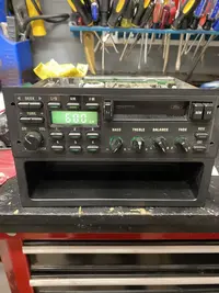
I got my hands on a factory radio which I’d like to bench test to see if it works before the installation. I never bench tested a radio before so before I do so I wanted to run it by you all to see if my plan would work or not. I obviously do not want to fry the radio.
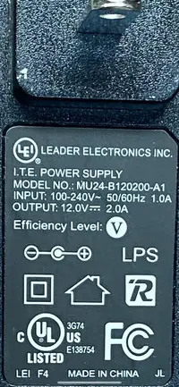
I plan to take a power cord from an old
Computer router, cut the end and splice the wires to the radio power. The router power cord says input 100-240v and output 12v so I’m thinking this may work unless the radio is actually less than 12v. I have super minimal electrical experience so before I do this and chance frying the radio I wanted to check. Any advice is appreciated.
 

Attachments

  • 15B20C8B-E434-465E-B712-EB022CEC4026.jpeg
    15B20C8B-E434-465E-B712-EB022CEC4026.jpeg
    411.3 KB · Views: 59
  • 2D411EAD-7459-4D6C-A9C5-EDFC67688D4D.png
    2D411EAD-7459-4D6C-A9C5-EDFC67688D4D.png
    6.1 MB · Views: 63
  • Sponsors (?)


First, some amps do not react well to not having speakers hooked up. To do this right, I’d want a pigtail correct to the radio, a wiring diagram, and 4 speakers hooked up right before applying power.
2 amps should be enough to light the clock, but not turn up the radio.
 
First, some amps do not react well to not having speakers hooked up. To do this right, I’d want a pigtail correct to the radio, a wiring diagram, and 4 speakers hooked up right before applying power.
2 amps should be enough to light the clock, but not turn up the radio.
Thank you for this info. I didn’t know about the 2 amp thing (not enough to power the speakers) so I guess even with speakers hooked up this would be pointless other than to see if the screen lights up. I will have to keep researching this for a better plan.
 
Ok after reading all the advice I decided that I’m going to do this the right way and get my hands on one of these converters instead of rigging my own power supply. Seems to be a safer bet. I’m feeling restless today so wanted to rig something quick in the basement but I now see I better slow down and do this differently before I fry the radio. I will see a friend that has one of these converters and get some fuses. Thanks!
 
First, thanks for the advice guys! I held out from making my own power line and picked up a desktop converter and wire diagram as suggested.

UPDATE: I’m in business! She powers up and makes noise! Tape deck is working and I will see about the stations when it’s installed in the car with an antenna. Right now just static while on the bench so I’m sure it will be fine.
As for the lights, everything illuminates however the clock/station indicator is so dim you can barely see it. Not even when the room is pitch black. I’ve read in the past that there are bulbs inside for that screen? I will look into this and try to solve that issue as well. This was the last piece of the puzzle in trying to get this thing back to stock condition (other than gears and exaust) in case anyone is wondering why I would be putting an old factory radio back in. Lol
Thanks again for the info and advice!
 
  • Like
Reactions: 1 user
Ok so sylvania bulb #24 doesn’t work. Not sure if it’s my radio or the bulb. Someone posted in the past that #24 worked for them but unfortunately not for me. I ordered what is advertised to be the correct bulb from a company online. Will have to wait until it arrives to see. A bit pricey but that’s the price sometimes of trying to get things right. Anyway, see pics below for the bulbs that didn’t work and the bulb I ordered and the radio with the cover off showing where the bulb is located if anyone is interested.
 

Attachments

  • 04C61D53-CAB2-47BA-AB6F-759B0D677F46.jpeg
    04C61D53-CAB2-47BA-AB6F-759B0D677F46.jpeg
    765.6 KB · Views: 57
  • 4D69168A-B766-4045-BE65-21B3761AB2B0.jpeg
    4D69168A-B766-4045-BE65-21B3761AB2B0.jpeg
    615.8 KB · Views: 55
  • 403A5E83-C326-4117-A85D-C04D755DA433.png
    403A5E83-C326-4117-A85D-C04D755DA433.png
    813.1 KB · Views: 58
Update:
Sorry for this confusion but maybe someone can give an opinion on how I should proceed.
So I canceled the new bulb order to that company that makes the specific bulb for the radio because I actually got the Sylvania #24 to work! But here’s the thing..... I followed a YouTube video which said to connect a lead to the 5th prong down in the back of the radio where the black harness connects and then to connect the lead to the positive side of a 9V battery then ground the negative side of the battery to the radio box to test the light bulb. I did this and it came on! Therefore my screen will now work with bulb #24 if I get power to the orange wire with the black tracer which is the wire going to the 5th prong down on the harness while i bench test. Before I do this though I wanted to check with you guys about twisting that wire together with the constant power wire, the illumination wire and the switched power wire which is all getting 12v. I don’t want to connect the orange/black wire for this light if it will blow the radio. Does anyone have any info on this? Sorry if I’m not explaining this right but the bottom line in the bulb works but doesn’t go on when I bench test because that lead isn’t connected to any power so I’m wondering if anyone knows specifically about this orange with with the black stripe if i can send 12v to it direct even though during the test only a 9v was needed to power the light. The wire diagram I have doesn’t show what that orange wire black stripe does. It’s left off the list.
9v negative terminal grounded to radio and 9v positive terminal connected to orange wire with black stripe on harness which is the 5th prong down from the top and the screen bulb lights (bulb #24).
 

Attachments

  • D264E64D-1A17-40E9-88B2-1C69B64B40B2.jpeg
    D264E64D-1A17-40E9-88B2-1C69B64B40B2.jpeg
    565.5 KB · Views: 52
From what I remember about my stock radio, the light changed intensity, I don't remember if it got brighter when the headlights were turned on or got dimmer but it definitely changed, that may have something to do with it.
 
Ok so for bench testing purposes I twisted the bulb wire (orange with black lead) together with the power wires (constant and switched) as well as the illumination wire. It’s working 100%! Was concerned of blowing something but she’s powered up perfect. Now I have to transpose the wires to what’s going on behind the dash after disconnecting the aftermarket radio. Now at least I know for sure my power, light and speaker wires on the factory radio to make it work so hopefully can match it to the car wires. Thanks everyone! The relay to dim the screen makes sense. Half the battle is done now. Long but productive day.
 

Attachments

  • 91DA1C80-2971-4B10-87F2-311BF1AAC708.jpeg
    91DA1C80-2971-4B10-87F2-311BF1AAC708.jpeg
    440.6 KB · Views: 61
  • Like
Reactions: 1 user
I still have the original radio and amp and wiring. I've considered sticking it back in but it only has a cassette player, someone here has a write up on installing a factory taurus (I think?) CD player, I'd do this.
 
I still have the original radio and amp and wiring. I've considered sticking it back in but it only has a cassette player, someone here has a write up on installing a factory taurus (I think?) CD player, I'd do this.
I have also seen this about a stock Ford radio but with a CD player. Guys were successful in making it work. You can do it. Just takes research I guess to figure it out but a great idea and can be done for sure!