Electrical Car dosen't run without jumping the EEC IV test port

Hey guys!

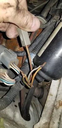
I am having a problem with a 1990 5.0L LX, 5 speed, hatchback. When I got the car, I noticed the EEC IV test port had been cut off and the wires were twisted together. This led to two discoveries...

1. If I undo either set of wires, the car dies.
2. The color of the wires that are there, do not match any wiring diagram I can find.

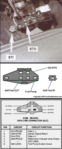
The Ford wiring diagram shows there should only be three wires going into the large plug and one into the STI plug. Their diagram shows a black/white, tan and tan/light green into the large plug, with the STI having a white/red wire.

This car has a tan, two tan/light green and gray/red for a total of 4 wires that are where the large plug was, with the STI having a tan/red.

I tested the voltage at the wires individually and found they are all dead with the ignition off and the following with the ignition on:

Tan - 11.88v
Tan/green #1 - 1.17v
Tan/green #2 - 12.27v
Gay/red - 4.87v

STI - 4.91v

I then tested the pairs when twisted together...

Tan crossed with gray/red - 6.28v
Tan/green #1 crossed with #2 - 12.27v

Being the Tan originally had 11.88 volts and the gray/red had 4.87 volts, there was a voltage drop with them twisted together.

The STI had 4.91v with the ignition on and .03v with the ignition off.

Any help identifying these wires and why the car won't run with them separated would be greatly appreciated!

Thank you everyone in advance for any help!
 

Attachments

  • 20240213_181505.jpg
    20240213_181505.jpg
    371.7 KB · Views: 38
  • 20240213_181549.jpg
    20240213_181549.jpg
    286.5 KB · Views: 33
  • Sponsors (?)


Large Connector
Tan Wire - Check Engine Light (Pin 17 on the ECU)
Tan/Gr Wire - Fuel pump test. The ground to trigger the fuel pump relay come from Pin 22 on ECU. This wire also goes to the fuel pump relay so that when you manually ground it and the key is on the fuel pump will run. If my memory serves me correctly the wire from the ECU goes to this large connector and then goes do the fuel pump relay under the driver seat so that is why you are seeing the two wires and why they have to be connected.

STI Connector
Wht / Red Wire - Goes back to the ECU and when grounded put the ECU in test mode (PIN 48). If you put power to this it will burn a trace in the ECU. My guess is the primary color on the wire has tinted with age and if you gently used some hand cleaner and a rag to clean it you would see that it is indeed Wht/Red.

As for the Gr/Red wire I do not have my wiring diagrams with me so I am of no help on that one but the VREF from the ECU is 5.0V+ so 4.87V+ is really close to that.
 
  • Like
  • Agree
Reactions: 1 users
Large Connector
Tan Wire - Check Engine Light (Pin 17 on the ECU)
Tan/Gr Wire - Fuel pump test. The ground to trigger the fuel pump relay come from Pin 22 on ECU. This wire also goes to the fuel pump relay so that when you manually ground it and the key is on the fuel pump will run. If my memory serves me correctly the wire from the ECU goes to this large connector and then goes do the fuel pump relay under the driver seat so that is why you are seeing the two wires and why they have to be connected.

STI Connector
Wht / Red Wire - Goes back to the ECU and when grounded put the ECU in test mode (PIN 48). If you put power to this it will burn a trace in the ECU. My guess is the primary color on the wire has tinted with age and if you gently used some hand cleaner and a rag to clean it you would see that it is indeed Wht/Red.

As for the Gr/Red wire I do not have my wiring diagrams with me so I am of no help on that one but the VREF from the ECU is 5.0V+ so 4.87V+ is really close to that.
Thank you for the help AeroCoupe!

So at minimum it sounds like there is a ground issue with either the ECU or the main harness for the fuel pump? Would that sound logical?

But I'm still not sure why the car dies if the gray and tan are disconnected. Could the gray/red be the ignition lead?
 
Everybody on here recommends sending 30+ year old ECU's to ECU exchange....
Sounds like something isn't working right and the previous owner was having the same problem??
 
  • Agree
Reactions: 1 user
Any wiring mods or hacks? Besides those wires of course.
There are several computer grounds in the engine compartment you need to check, sending the computer in to the Exchange is a good idea, also check to be sure it has the correct computer in it.
There is a ground in the injector harness (orange wire I think) that bolts to the intake or head on the right side under the throttle body, one on the inner fender between the battery and the solenoid, and a ground bolted to the back of the head and the firewall on the drivers side (this is mostly for the gauges).
 
  • Like
Reactions: 2 users
The Tan/light green wires control the fuel pump. I think what is happening here is normally both those wires go under the same crimped pin in the ecu connector. Look at connection C135 below. I bet one wire (prob tan/green #1 without voltage) will ring out continuity to pin 22 on the ECU, and the other wire (tan green 2 with 12V) will ring out to the tan/LG wire on the fuel pump relay under the seat. So these wires would be connected on the original ECU connector to have the pump run. Grounding these will test the fuel pump which is what happens with you ground out C1984. This is an '88 diagram, so i'll check the '90 one later.

Is the fuel pump controlled by the ECU. If you turn key to ON, does it cycle for 2 seconds and stop?

1708097242672.png


I have the STI is a tan/red single pin wire
1708097353323.png


Not sure why the other wires are twisted. The light tan wire just flashes the CEL and is pin 17. It likely has 12V on it because the CEL is on? Car should run with this disconnected. The other wire should be the pin 46 sensor ground, but I don't have the wire color for 1990 in front of me. In that case, it looks like they spliced it with the check engine light switched ground. This doesn't make sense to me however. WOuld need to dig around a bit more on this.
 
I thought about sending out the ECU. Kinda wondered if there might be an internal problem with it. It is the correct A9L. The car is basically bone stock with the exception of cat back exhaust. I also wondered if the EEC power relay could have anything to do with it. It looks original.

The fuel pump does charge for 2-3 seconds when the key is turned on, but only with the two wires twisted together. If they are undone, I get nothing.

I have a spare A9L (technically an A3M1) sitting around, but I was afraid to plug it in, being there may be another issue.

I'm glad to finally see somewhere that the STI is the correct color. I was starting to worry someone had changed out engine harnesses for the wrong one.

I'm going to start checking those grounds and I'll post an update with my findings.

Thanks again everyone!
 
Here you go. I got the proper 1990 wiring diagram. The two tan/green wires are supposed to be connected at the test connector. So two wires under one terminal.

Wire 97
IMG_7959.jpeg


And here’s the text connector pinout
IMG_7958.jpeg
 
You’re missing the black/white wire. Any chance it’s tucked or cut back somewhere?

That grey/red wire is not part of the test connector it seems.


Tan is the actual check engine light which has constant 12v. It’s supposed to connect to pin 17 which is a switched ground so when the ECU closes it, you get the cel. At the test connector it’s just dead-ended as it’s supposed to connect to the test equipment and show the cel when the pin 17 closes.

My guess is they are stealing 12v from the cel in order to power something else. Haven’t identified what yet.

The two tan/green wires are supposed to be connected together.

Need to find what the gray/red wire is for.
 
Last edited:
Here’s the cel wiring for a visual.

The cel bulb has constant 12v. It’s activated by switching the ground on pin 17
IMG_7960.jpeg


So the tan wire at the test connector should dead end with no connection.
IMG_7961.jpeg


My guess is they are stealing the 12v to power something else on that gray/red.


Also, I don’t suspect you have a bad ECU. I suspect some hackery in the wiring.
 
  • Useful
Reactions: 1 user
I show the same in the 1993 EVTM.

Guess that’s more evidence Ford was inconsistent with their wire colors for these cars and that the wiring diagrams (EVTM) don’t always match.
IMG_7957.jpeg


So now the question is why does the car only run with sensor ground connected to the cel wire?

The other two tan/green wires are supposed to be connected for car to run
 
Last edited:
  • Like
Reactions: 1 users
I found the attached diagram that shows the gray/red as a signal wire... though I don't really know what that does. Nor do I know what the attached diagram is for (Mustang, Crown Vic, etc).

I looked at friend's '90 GT and you guys are correct, the two tan/green share a pin and the tan and gray/red have their own. Oddly, it does not have the black/white wire either, as most Ford wiring diagrams indicate for the 1990 model year.

I'm kinda leaning towards the ECU as well. I guess I will take my other A9L and put it in and see what happens. I'll report back as soon as I can try it.

Thank you guys for all of the input! It has helped.
 

Attachments

  • Screenshot_20240217-005504_Chrome.jpg
    Screenshot_20240217-005504_Chrome.jpg
    469.1 KB · Views: 18
Like someone already said, sounds like someone did something stupid and burned up the ECU and the only way to keep it running is by twisting those wires.

I literally just got a computer back from ECu xchange,man those people are a dream to work with, if you need to get your ECU repaired, that's the only place to send it.
 
  • Like
  • Agree
Reactions: 2 users