
Code 85 CANP solenoid - The Carbon Canister solenoid is inoperative or missing.
Revised 11 –Jan_2015 to add warning about vacuum leaks due to deteriorated hose or missing caps on vacuum lines when the solenoid is removed.
Check vacuum lines for leaks and cracks. Check electrical wiring for loose connections, damaged wiring and insulation. Check solenoid valve operation by grounding the gray/yellow wire to the solenoid and blowing through it.
The computer provides the ground for the solenoid. The red wire to the solenoid is always energized any time the ignition switch is in the run position.
If you disconnected the carbon canister and failed to properly cap the vacuum line coming from under the upper intake manifold, you will have problems. You will also have problems if the remaining hose coming from under the upper intake manifold or caps for the vacuum line are sucking air.
Charcoal canister plumbing - one 3/8" tube from the bottom of the upper manifold to the rubber hose. Rubber hose connects to one side of the canister solenoid valve. Other side of the solenoid valve connects to one side of the canister. The other side of the canister connects to a rubber hose that connects to a line that goes all the way back to the gas tank. There is an electrical connector coming from the passenger side injector harness near #1 injector that plugs into the canister solenoid valve. It's purpose is to vent the gas tank. The solenoid valve opens at cruse to provide some extra fuel. The canister is normally mounted on the passenger side frame rail near the smog pump pulley.
Connecting the gas tank vent line directly to the intake manifold will result in fuel vapor being constantly sucked into the intake manifold. There is unmetered fuel that the computer cannot adjust for. The result is poor idle and poor fuel economy.
It does not weigh but a pound or so and helps richen up the cruse mixture. It draws no HP & keeps the car from smelling like gasoline in a closed garage. So with all these good things and no bad ones, why not hook it up & use it?
The purge valve solenoid connector is a dangling wire that is near the ECT sensor and oil filler on the passenger side rocker cover. The actual solenoid valve is down next to the carbon canister. There is about 12"-16" of wire that runs parallel to the canister vent hose that comes off the bottom side of the upper intake manifold. That hose connects one port of the solenoid valve; the other port connects to the carbon canister.
The purge valve solenoid should be available at your local auto parts store.
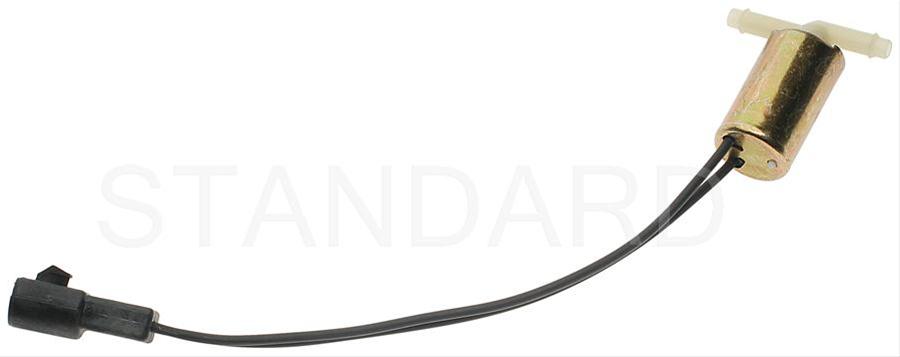
Purge valve solenoid:
The carbon canister is normally mounted on the passenger side frame rail near the smog pump pulley.
Carbon Canister:

Codes 44 & 94 - AIR system inoperative - Air Injection. Check vacuum lines for leaks, & cracks. Check for a clogged air crossover tube, where one or both sides of the tube clog with carbon.
Revised 21 Sep 2012 to correct the description of the process that sets the code and include Thermactor Air System diagram.
If you have a catalytic converter H pipe, you need to fix these codes. If you don't, then don't worry about them.
Code 44 passenger side air not functioning.
Code 94 driver side air not functioning.
The TAD solenoid/TAD diverter valve directs smog pump output to either the crossover tube attached to the cylinder heads or to the catalytic converters.
The O2 sensors are placed before the catalytic converters, so they do not see the extra O2 when the smog pump's output is directed to the converters or the input just before the converter.
The 44/94 code uses the O2 sensors to detect a shift in the O2 level in the exhaust. The smog pump provides extra air to the exhaust which raises the O2 level in the exhaust when the smog pump output is directed through the crossover tube.
When there is an absence of increase in the O2 levels when the TAD solenoid/TAD diverter valve directs air through the crossover tube, it detects the lower O2 level and sets the code.
Failure mode is usually due to a clogged air crossover tube, where one or both sides of the tube clog with carbon. The air crossover tube mounts on the back of the cylinder heads and supplies air to each of the Thermactor air passages cast into the cylinder heads. When the heads do not get the proper air delivery, they set codes 44 & 94, depending on which passage is clogged. It is possible to get both 44 & 94, which would suggest that the air pump or control valves are not working correctly, or the crossover tube is full of carbon or missing.
Testing the system:
Note that the engine must be running to do the tests unless stated otherwise. For safety’s sake, do test preparation like loosening clamps, disconnecting hoses and connecting things to a vacuum source with the engine off.
Disconnect the big hose from smog pump: with the engine running you should feel air output. Reconnect the smog pump hose & apply vacuum to the first vacuum controlled valve: Its purpose is to either dump the pump's output to the atmosphere or pass it to the next valve.
The next vacuum controlled valve directs the air to either the cylinder heads when the engine is cold or to the catalytic converter when the engine is warm. Disconnect the big hoses from the back side of the vacuum controlled valve and start the engine. Apply vacuum to the valve and see if the airflow changes from one hose to the next.
The two electrical controlled vacuum valves mounted on the rear of the passenger side wheel well turn the vacuum on & off under computer control. Check to see that both valves have +12 volts on the red wire. Then ground the white/red wire and the first solenoid should open and pass vacuum. Do the same thing to the light green/black wire on the second solenoid and it should open and pass vacuum.
Remember that the computer does not source power for any actuator or relay, but provides the ground necessary to complete the circuit. That means one side of the circuit will always be hot, and the other side will go to ground or below 1 volt as the computer switches on that circuit.
The following computer tests are done with the engine not running.
The computer provides the ground to complete the circuit to power the solenoid valve that turns the
vacuum on or off. The computer is located under the passenger side kick panel. Remove the kick panel & the cover over the computer wiring connector pins. Check Pin 38 Solenoid valve #1 that provides vacuum to the first Thermactor control valve for a switch from 12-14 volts to 1 volt or less. Do the same with pin 32 solenoid valve #2 that provides vacuum to the second Thermactor control valve. Turning the ignition to Run with the computer jumpered to self-test mode will cause all the actuators to toggle on and off. If after doing this and you see no switching of the voltage on and off, you can start testing the wiring for shorts to ground and broken wiring. An Ohm check to ground with the computer connector disconnected & the solenoid valves disconnected should show open circuit between the pin 32 and ground and again on pin 38 and ground. In like manner, there should be less than 1 ohm between pin 32 and solenoid valve #2 and pin 38 & Solenoid valve #1.
The following computer tests are done with the engine running.
If after checking the resistance of the wiring & you are sure that there are no wiring faults, start looking at the solenoid valves. If you disconnect them, you can jumper power & ground to them to verify operation with the engine running. Power & ground supplied should turn on the vacuum flow, remove either one and the vacuum should stop flowing.
Typical resistance of the solenoid valves is in the range of 20-70 Ohms.
See the following website for some help from Tmoss (diagram designer) & Stang&2Birds (website host)
http://www.veryuseful.com/mustang/tech/engine/images/fuel-alt-links-ign-ac.gif
http://www.veryuseful.com/mustang/tech/engine/images/88-91eecPinout.gif
If you have a catalytic converter H pipe, you need to fix these codes. If you don't, then don't worry about them
The following are diagrams courtesy of Tmoss & Stang&2birds
Complete computer, actuator & sensor wiring diagram for 91-93 Mass Air Mustangs
Engine mounted fuel injector harness
5.0 wiring diagram for Fuel Injectors, Sensors, and Actuators
See the following website for some help from Tmoss (diagram designer) & Stang&2Birds (website host) for help on 88-95 wiring; http://www.veryuseful.com/mustang/tech/engine/ Everyone should bookmark this site.
TFI module wiring for 94-95 Mustang GT
http://www.veryuseful.com/mustang/tech/engine/images/Mustang-94-95-IgnitionControlModule.gif
Complete computer, actuator & sensor wiring diagram for 94-95 Mustangs
Complete computer, actuator & sensor wiring diagram for 91-93 Mass Air Mustangs
Complete computer, actuator & sensor wiring diagram for 88-90 Mass Air Mustangs
5.0 wiring diagram for Fuel Injectors, Sensors, and Actuators
Main body EFI wiring harness
Ignition switch wiring
O2 sensor wiring harness
Vacuum diagram 89-93 Mustangs
HVAC vacuum diagram
TFI module differences & pin out
Fuse box layout
Mustang 5.0 Lights and Radio schematic, by TMoss:
http://www.veryuseful.com/mustang/tech/engine/images/mustangFoxLights-Radio_diag.gif
87-92 power window wiring
93 power window wiring
T5 Cutaway showing T5 internal parts
Visual comparison of the Ford Fuel Injectors, picture by TMoss:
Convertible top motor wiring
http://www.veryuseful.com/mustang/tech/engine/images/mustang88VertTopMotorCkt.gif
Engine mounted fuel injector harness
Location of the TPS, IAB, and the 10-pin connectors on a 5.0, picture by TMoss:
Starter circuit
Alternator diagram for 94-95 Mustangs.

