
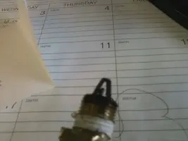
I have been up and down the surging idle checklist, and checked vacuum (at 19) It wont die everytime and when in open loop she acts like a Champ. I have replaced The O2 sensors the ACT and ECT sensors, cleared all codes, cleaned the IAC, cleaned the PCV. I've put off asking for help but finally had a new symptom on the way to work this morning. I kicked her in the guts a bit in second gear and she seemed to get up and go, then out of nowhere she started pulling even harder like a small shot of nitrous. Could this be my TPS sensor? I dont have a DVM so I cant run a diagnostic on it. I do however have an old spare that came with the car when I bought it. Its a bit chewed up, but I could throw it on there and see.
You are using an out of date browser. It may not display this or other websites correctly.
You should upgrade or use an alternative browser.
You should upgrade or use an alternative browser.
Dies at stop lights after warm up
- Thread starter darthcual
- Start date
The reason the "Surging Idle Checklist doesn't work for some people is because they read some of it but do very little of it.
What codes did you get? Post the code numbers and I will give you the 5.0 Mustang specific fixes.
Have you checked the ignition timing with a timing light?
Get out your wallet, go to Home Depot and buy an inexpensive DVM. It will cost less than some of the other things you have spent money on... Use it to check the TPS voltage. See the sticky http://www.stangnet.com/mustang-forums/825424-adjusting-your-tps-0-98v-not-necessary.html for information on how to correctly test and set the TPS.
The reason the "Surging Idle Checklist doesn't work for some people is because they read some of it but do very little of it.
What codes did you get? Post the code numbers and I will give you the 5.0 Mustang specific fixes.
Have you checked the ignition timing with a timing light?
Get out your wallet, go to Home Depot and buy an inexpensive DVM. It will cost less than some of the other things you have spent money on... Use it to check the TPS voltage. See the sticky http://www.stangnet.com/mustang-forums/825424-adjusting-your-tps-0-98v-not-necessary.html for information on how to correctly test and set the TPS.
I can assure you, outside of testing with a DVM I have gone thru the whole checklist. Just noticed on the way home that if I bump the ignition cylinder (which I've recently replaced because the old one would turn without a key) the car dies. Not even turning it to the off position. So next time I experience the surge I will play with that and see if it is the cause. Timing has been set recently and I dont feel terrible for replacing the sensors as they were toast (except for the ECT, although it had a ford part # and ,appeared to be factory original.
Codes are cleared and gone but here they are because you asked , 31,82,84,91. The EGR were because I forgot to plug the electrical connection back in, and the 91 was a bad o2 ground that I relocated to the firewall.
Attachments
So after work I took another quick look. While the surge was happening I unplugged the the vac line from the FPR and the idle smoothed right out. Put my finger over the line and it starts surging. I have no idea what this means though.
To further the arguement of a bad FPR I smell gas and the PCV valve was caked up with gasoline varnish, when it turns gellatinous and congeals before it hardens.
Check to see if the FPR vacuum line has gas in it. If it does, the FPR diaphram is leaking gas back into the engine by sucking it into the intake manifold..
Try disconnecting another vacuum line and see if you get similar symptoms.
Did you clear the codes after replaing the O2 sensors?
Try disconnecting another vacuum line and see if you get similar symptoms.
Did you clear the codes after replaing the O2 sensors?
Yes the code(s) were gone after I made the repairs. No gas in the vac line leading to the intake. I pulled the fuel rail last night and noticed that the injectors are not stock. They are Python Orange tops which I looked up and appear to be 24lb injectors. The P.O. also has a Pro-M MAF on the car and I guess its the one tuned for a CAI and larger injectors. IDK for certain because the part # is gone. Still stumped as it was running fine for a few months before it started dying at stoplights/stop signs. Here is where I stand:

I have an intake that I want to put on and I figured now is the best time while I have everything apart. Notice the Heads have coolant leaking into them on the intake in the front and back. Now I know where my coolant has been going. It doesnt appear it was the the gasket but the bolts that go thru the intake into the water jacket. No white smoke blowing but a faint smell of radiator fluid.
I have an intake that I want to put on and I figured now is the best time while I have everything apart. Notice the Heads have coolant leaking into them on the intake in the front and back. Now I know where my coolant has been going. It doesnt appear it was the the gasket but the bolts that go thru the intake into the water jacket. No white smoke blowing but a faint smell of radiator fluid.
Attachments

Code 91 and an engine that smooths out when you create a vacuum leak. That says rich mixture, and is probably the source of your idle problem.
Code 41 or 91 Three digit code 172 or 176 - O2 sensor indicates system lean. Look for a vacuum leak or failing O2 sensor.
Revised 22-Jun-2009 to include 3 digit code and wiring for 94-95 5.0 Mustangs
Code 41 is a RH side sensor,
Code 91 is the LH side sensor.
Code 172 is the RH side sensor
Code 176 is the LH side sensor
The computer sees a lean mixture signal coming from the O2 sensors and tries to compensate by adding more fuel. Many times the end result is an engine that runs pig rich and stinks of unburned fuel.
The following is a Quote from Charles O. Probst, Ford fuel Injection & Electronic Engine control:
"When the mixture is lean, the exhaust gas has oxygen, about the same amount as the ambient air. So the sensor will generate less than 400 Millivolts. Remember lean = less voltage.
When the mixture is rich, there's less oxygen in the exhaust than in the ambient air , so voltage is generated between the two sides of the tip. The voltage is greater than 600 millivolts. Remember rich = more voltage.
Here's a tip: the newer the sensor, the more the voltage changes, swinging from as low as 0.1 volt to as much as 0.9 volt. As an oxygen sensor ages, the voltage changes get smaller and slower - the voltage change lags behind the change in exhaust gas oxygen.
Because the oxygen sensor generates its own voltage, never apply voltage and never measure resistance of the sensor circuit. To measure voltage signals, use an analog voltmeter with a high input impedance, at least 10 megohms. Remember, a digital voltmeter will average a changing voltage." End Quote
Testing the O2 sensors 87-93 5.0 Mustangs
Measuring the O2 sensor voltage at the computer will give you a good idea of how well they are working. You'll have to pull the passenger side kick panel off to gain access to the computer connector. Remove the plastic wiring cover to get to the back side of the wiring. Use a safety pin or paper clip to probe the connections from the rear. The computer pins are 29 (LH O2 with a dark green/pink wire) and 43 (RH O2 with a dark blue/pink wire). Use the ground next to the computer to ground the voltmeter. The O2 sensor voltage should switch between .2-.9 volt at idle.
Testing the O2 sensors 94-95 5.0 Mustangs
Measuring the O2 sensor voltage at the computer will give you a good idea of how well they are working. You'll have to pull the passenger side kick panel off to gain access to the computer connector. Remove the plastic wiring cover to get to the back side of the wiring. Use a safety pin or paper clip to probe the connections from the rear. The computer pins are 29 (LH O2 with a red/black wire) and 27 (RH O2 with a gray/lt blue wire). Use pin 32 (gray/red wire) to ground the voltmeter. The O2 sensor voltage should switch between .2-.9 volt at idle.
Note that all resistance tests must be done with power off. Measuring resistance with a circuit powered on will give false readings and possibly damage the meter. Do not attempt to measure the resistance of the O2 sensors, it may damage them.
Testing the O2 sensor wiring harness
Most of the common multimeters have a resistance scale. Be sure the O2 sensors are disconnected and measure the resistance from the O2 sensor body harness to the pins on the computer.
The O2 sensor ground (orange wire with a ring terminal on it) is in the wiring harness for the fuel injection wiring. I grounded mine to one of the intake manifold bolts
Make sure you have the proper 3 wire O2 sensors. Only the 4 cylinder cars used a 4 wire sensor, which is not compatible with the V8 wiring harness.
Replace the O2 sensors in pairs if replacement is indicated. If one is weak or bad, the other one probably isn't far behind.
If you get only code 41 and have changed the sensor, look for vacuum leaks. This is especially true if you are having idle problems. The small plastic tubing is very brittle after many years of the heating it receives. Replace the tubing and check the PVC and the hoses connected to it.
A secondary problem with only a code 41 is for cars with an intact smog pump and cats. If the tube on the back of the heads clogs up the driver’s side, all the air from the smog pump gets dumped into one side. This excess air upsets the O2 sensor calibration and can set a false code 41. The cure is to remove the crossover tube and thoroughly clean the insides so that there is no carbon blocking the free flow of air to both heads.
Intake manifold installation tips:
Whatever you do, don't skimp on cleaning the gasket surfaces. New gaskets need to seat against bare metal and not the residue left from the old gaskets in order to seal leak free. This is the most time consuming and tiresome part of the job. Put a piece of cardboard in the lifter valley to cover it up. It will reduce the amount that falls down into the valley and hydraulic lifters. I suggest that you make good use of a shop vac while you are scraping and cleaning to avoid getting the old gasket material lost inside the engine. Look for little things that need to be replaced like the short hose from the thermostat hosing to the water pump, damaged vacuum lines and hose clamps that are rusted or broken.
Plan on cutting the thermostat to water pump hose, or removing the thermostat housing. Also plan on removing the distributor to get clearance to remove the intake manifold. Remove #1 spark plug, stick your finger in the spark plug hole and crank. When your finger gets air moving past it, stop cranking. Turn the engine until the timing marks line up with the pointer. Now you can pull the distributor out.
My favorite trick that saves time and effort is the stay in place gasket. Be sure that you scrape (don't use a wire brush) all the old gasket material off, then clean all the surfaces with acetone or MEK.
When the surfaces are clean, use weather strip adhesive on the head to manifold surface. Also use the weather strip adhesive on the side of the gasket that mates to the head. When you are done, the head surface and the gasket surface that mate together will have weather strip adhesive on them. Follow the instructions on the tube or can and when it gets tacky, press the gasket down on the head.
Clean the area where the rubber rails mount to the block in front and in the rear with more acetone or MEK and do the same trick with the weather strip adhesive that you did to the heads.
Coat the rubber seals and the gasket area around the water passages with lots of Blue Silicone gasket sealer and put it together. Bingo! no leaks, and no gaskets that shifted out of place.
If you reuse the injectors from your old setup, a repair kit is available from most auto parts stores if needed. Coat the injector body "O" rings with oil before you use them and everything will slide back together.
Fuel injector seal kits with 2 O rings and a pintle cap (Borg-Warner P/N 274081) are available at Pep Boys auto parts. Cost is about $3.50 - $4.00 per kit. The following are listed at the Borg-Warner site ( BWD - Home ) as being resellers of Borg-Warner parts:
Welcome to PartsPlus.com or Auto Value / Bumper to Bumper Quality Parts & Service - Home of the Aftermarket Auto Parts Alliance Group or Auto Parts Stores, Brakes, Tires & Automotive Parts | Pep Boys or Federated Auto Parts - Automotive Aftermarket
Most of the links above have store locators for find a store in your area.
Use motor oil on the O rings when you re-assemble them & everything will slide into place. The gasoline will wash away any excess oil that gets in the wrong places and it will burn up in the combustion chamber.
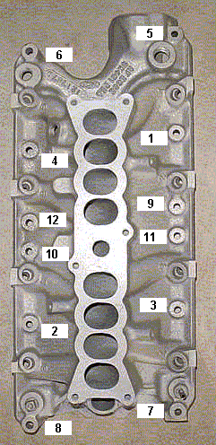
Intake manifold to head bolts
--Step 1 96 in/lbs
--Step 2 16ft/lbs
--Step 3 23-25 ft/lbs
Code 41 or 91 Three digit code 172 or 176 - O2 sensor indicates system lean. Look for a vacuum leak or failing O2 sensor.
Revised 22-Jun-2009 to include 3 digit code and wiring for 94-95 5.0 Mustangs
Code 41 is a RH side sensor,
Code 91 is the LH side sensor.
Code 172 is the RH side sensor
Code 176 is the LH side sensor
The computer sees a lean mixture signal coming from the O2 sensors and tries to compensate by adding more fuel. Many times the end result is an engine that runs pig rich and stinks of unburned fuel.
The following is a Quote from Charles O. Probst, Ford fuel Injection & Electronic Engine control:
"When the mixture is lean, the exhaust gas has oxygen, about the same amount as the ambient air. So the sensor will generate less than 400 Millivolts. Remember lean = less voltage.
When the mixture is rich, there's less oxygen in the exhaust than in the ambient air , so voltage is generated between the two sides of the tip. The voltage is greater than 600 millivolts. Remember rich = more voltage.
Here's a tip: the newer the sensor, the more the voltage changes, swinging from as low as 0.1 volt to as much as 0.9 volt. As an oxygen sensor ages, the voltage changes get smaller and slower - the voltage change lags behind the change in exhaust gas oxygen.
Because the oxygen sensor generates its own voltage, never apply voltage and never measure resistance of the sensor circuit. To measure voltage signals, use an analog voltmeter with a high input impedance, at least 10 megohms. Remember, a digital voltmeter will average a changing voltage." End Quote
Testing the O2 sensors 87-93 5.0 Mustangs
Measuring the O2 sensor voltage at the computer will give you a good idea of how well they are working. You'll have to pull the passenger side kick panel off to gain access to the computer connector. Remove the plastic wiring cover to get to the back side of the wiring. Use a safety pin or paper clip to probe the connections from the rear. The computer pins are 29 (LH O2 with a dark green/pink wire) and 43 (RH O2 with a dark blue/pink wire). Use the ground next to the computer to ground the voltmeter. The O2 sensor voltage should switch between .2-.9 volt at idle.
Testing the O2 sensors 94-95 5.0 Mustangs
Measuring the O2 sensor voltage at the computer will give you a good idea of how well they are working. You'll have to pull the passenger side kick panel off to gain access to the computer connector. Remove the plastic wiring cover to get to the back side of the wiring. Use a safety pin or paper clip to probe the connections from the rear. The computer pins are 29 (LH O2 with a red/black wire) and 27 (RH O2 with a gray/lt blue wire). Use pin 32 (gray/red wire) to ground the voltmeter. The O2 sensor voltage should switch between .2-.9 volt at idle.
Note that all resistance tests must be done with power off. Measuring resistance with a circuit powered on will give false readings and possibly damage the meter. Do not attempt to measure the resistance of the O2 sensors, it may damage them.
Testing the O2 sensor wiring harness
Most of the common multimeters have a resistance scale. Be sure the O2 sensors are disconnected and measure the resistance from the O2 sensor body harness to the pins on the computer.
The O2 sensor ground (orange wire with a ring terminal on it) is in the wiring harness for the fuel injection wiring. I grounded mine to one of the intake manifold bolts
Make sure you have the proper 3 wire O2 sensors. Only the 4 cylinder cars used a 4 wire sensor, which is not compatible with the V8 wiring harness.
Replace the O2 sensors in pairs if replacement is indicated. If one is weak or bad, the other one probably isn't far behind.
If you get only code 41 and have changed the sensor, look for vacuum leaks. This is especially true if you are having idle problems. The small plastic tubing is very brittle after many years of the heating it receives. Replace the tubing and check the PVC and the hoses connected to it.
A secondary problem with only a code 41 is for cars with an intact smog pump and cats. If the tube on the back of the heads clogs up the driver’s side, all the air from the smog pump gets dumped into one side. This excess air upsets the O2 sensor calibration and can set a false code 41. The cure is to remove the crossover tube and thoroughly clean the insides so that there is no carbon blocking the free flow of air to both heads.
Intake manifold installation tips:
Whatever you do, don't skimp on cleaning the gasket surfaces. New gaskets need to seat against bare metal and not the residue left from the old gaskets in order to seal leak free. This is the most time consuming and tiresome part of the job. Put a piece of cardboard in the lifter valley to cover it up. It will reduce the amount that falls down into the valley and hydraulic lifters. I suggest that you make good use of a shop vac while you are scraping and cleaning to avoid getting the old gasket material lost inside the engine. Look for little things that need to be replaced like the short hose from the thermostat hosing to the water pump, damaged vacuum lines and hose clamps that are rusted or broken.
Plan on cutting the thermostat to water pump hose, or removing the thermostat housing. Also plan on removing the distributor to get clearance to remove the intake manifold. Remove #1 spark plug, stick your finger in the spark plug hole and crank. When your finger gets air moving past it, stop cranking. Turn the engine until the timing marks line up with the pointer. Now you can pull the distributor out.
My favorite trick that saves time and effort is the stay in place gasket. Be sure that you scrape (don't use a wire brush) all the old gasket material off, then clean all the surfaces with acetone or MEK.
When the surfaces are clean, use weather strip adhesive on the head to manifold surface. Also use the weather strip adhesive on the side of the gasket that mates to the head. When you are done, the head surface and the gasket surface that mate together will have weather strip adhesive on them. Follow the instructions on the tube or can and when it gets tacky, press the gasket down on the head.
Clean the area where the rubber rails mount to the block in front and in the rear with more acetone or MEK and do the same trick with the weather strip adhesive that you did to the heads.
Coat the rubber seals and the gasket area around the water passages with lots of Blue Silicone gasket sealer and put it together. Bingo! no leaks, and no gaskets that shifted out of place.
If you reuse the injectors from your old setup, a repair kit is available from most auto parts stores if needed. Coat the injector body "O" rings with oil before you use them and everything will slide back together.
Fuel injector seal kits with 2 O rings and a pintle cap (Borg-Warner P/N 274081) are available at Pep Boys auto parts. Cost is about $3.50 - $4.00 per kit. The following are listed at the Borg-Warner site ( BWD - Home ) as being resellers of Borg-Warner parts:
Welcome to PartsPlus.com or Auto Value / Bumper to Bumper Quality Parts & Service - Home of the Aftermarket Auto Parts Alliance Group or Auto Parts Stores, Brakes, Tires & Automotive Parts | Pep Boys or Federated Auto Parts - Automotive Aftermarket
Most of the links above have store locators for find a store in your area.
Use motor oil on the O rings when you re-assemble them & everything will slide into place. The gasoline will wash away any excess oil that gets in the wrong places and it will burn up in the combustion chamber.
Intake manifold to head bolts
--Step 1 96 in/lbs
--Step 2 16ft/lbs
--Step 3 23-25 ft/lbs
Well it looks like I made one mistake taking out the dizzy without marking or setting TDC. What do I need to do to resolve this?
Putting the distributor back in and setting the timing.
Putting the distributor back in is fairly simple. Pull #1 sparkplug, put your finger in the sparkplug hole,
crank the engine until you feel compression. Then line up the TDC mark on the balancer with the pointer on the engine block.
The distributor starts out with the #1 plug wire lined up at about 12:00 with you facing it. Align the rotor to about 11:00, since it will turn clockwise as it slides into place.
Align the distributor rotor up with the #1 position marked on the cap, slide the distributor down into the block, (you may have to wiggle the rotor slightly to get the gear to engage) and then note where the rotor is pointing.
If it still lines up with #1 position on the cap, install the clamp and bolt. If not, pull it out and turn 1 tooth forwards or backwards and try again. Put the #1 spark plug back in and tighten it down, put the clamp on the distributor, but don't tighten it too much, as you will have to move the distributor to set the timing. Note that there is no such thing as one tooth off on a 5.0 Mustang. If it doesn't align perfectly with #1 position, you can turn the distributor until it does. The only problem is that if you are too far one way or the other, you can't turn the distributor enough to get the 10-14 degree optimum timing range.
Setting the timing:
Paint the mark on the harmonic balancer with paint -choose 10 degrees BTC or 14 degrees BTC or something else if you have NO2 or other power adder. I try to paint TDC red, 10 degrees BTC white and 14 degrees BTC blue.
10 degrees BTC is towards the drivers side marks.
Simplified diagram of what it looks like. Not all the marks are shown for ease of viewing.
ATC ' ' ' ' ' ' ' ' ' '!' ' ' ' ' ' ' ' ' ' BTC
---------------- > Direction of Rotation as viewed standing in front of the engine.
The ' is 2 degrees.
The ! is TDC
The ' is 10 degrees BTC
Set the timing 5 marks BTC. Or if you prefer, 5 marks towards the driver's side to get 10 degrees.
To get 14 degrees, set it 7 marks BTC. Or if you prefer, 7 marks towards the driver's side to get 14 degrees.
The paint marks you make are your friends if you do it correctly. They are much easier to see that the marks machined into the harmonic balancer hub.
At this point hook up all the wires, get out the timing light. Connect timing light up to battery & #1 spark plug. Then start the engine.
Remove the SPOUT connector (do a search if you want a picture of the SPOUT connector) It is the 2 pin rectangular plug on the distributor wiring harness. Only the EFI Mustang engines have a SPOUT. If yours is not EFI, check for a SPOUT: if you don’t find one, skip any instructions regarding the SPOUT
Warning: there are only two places the SPOUT should be when you time the engine. The first place is in your pocket while you are setting the timing and the second is back in the harness when you finish. The little bugger is too easy to lose and too hard to find a replacement.
Start engine, loosen distributor hold down with a 1/2" universal socket. Shine the timing light on the marks and turn the distributor until the mark lines up with the edge of the timing pointer. Tighten down the distributor hold down bolt, Replace the SPOUT connector and you are done.
The HO firing order is 1-3-7-2-6-5-4-8.
Non HO firing order is 1-5-4-2-6-3-7-8
Thanks for all the help. But just once I'd like you to say, "You're F****D!" Off to the JY I go in search of gt40/gt40p's.
Similar threads
- Replies
- 1
- Views
- 126
- Replies
- 16
- Views
- 931
- Replies
- 20
- Views
- 867
- Replies
- 2
- Views
- 449