Electric fan install questions...

Ok so I've been researching on how to do the ele. fan swap. I'm buying the mark viii fan today/tomorrow. But I cant wait 4+ weeks for the DCControler to get here. So I'm gonna follow the instructions from this link on wiring it up:
Mark VIII Fan Install

My questions:
-Do I need any inline fuses?

-Where can I tap into a 12v key-on source in the engine bay? (The link states they "spliced into the wiring harness near the mass air meter". But I dont have MAF. So I dont know where the link is talking about!?!)

-Also the link says to use an 30amp relay. But I've read that people use a bosch 75amp relay. So which relay should I use?

Thanx
 
  • Sponsors (?)


Derale 16749 - Derale Deluxe Adjustable Controllers with Pipe Threaded Probes

i just installed my taurus fan with this controller, it worked out great, i was in the same boat as you not wanting to wait for the DCC unit, oneday i'll probly get one of those.

I was a little leary of the one i bought, i had it sitting in my basement for months and my taurus fan has been sitting there for like 2 or 3 years, but they are working great so far, i set the fan to come on around 170 degrees and when i shut the car off the fan stays on until the car is under the 170.
 
no you need to use at least 40 amp relay or a 30 amp, yes you need to put an inline fuse b/t the power and the relay.

you can get the 12V from alot of places but the easiest is at the radio
 
The Mark fans spike up to 90amps on startup...they need a much bigger fuse than the Taurus fans. I'm currently running a 125amp car stereo fuse setup with mine PLUS the plug/fuse setup that i got off of another Taurus fan (turned out the plugs were exactly the same, so the extra fuse is just good measure).

As for that write up...the whole test fitting stuff is overkill. Just trim 3/8 off the shroud. NO MORE, NO LESS. Measure twice, cut once and don't mess it up. If in doubt, cut 1/4 inch and see if that works for you and if not then cut another 1/8 extra. I trimmed 3/8 off mine and i have plenty of space between the water pump pulley and the fan.
 
Yeah that's just on start up...i'm not sure what it pulls while it's just running...startup is really crazy though. We found this out after blowing a few 60amp fuses.


I can't stress enough how important it is that you don't trim too much off the shroud. If you cut off too much the blades will contact your radiator and you'll have ruined the fan.
 
I've thought about it...but more to take the load off the alt than take the load from start up. I'm just too lazy to try it and i haven't noticed any drawbacks to not doing it.
 
The battery has plenty of reserve for the start-up draw. It's just a burden on the wiring and makes fusing cumbersome. I like to use links instead of fuses.
 
OK so I finally made up my mind with all the info I gathered....

I'm gonna wire in 2) 30/40amp relays in parallel with each other. That'll make it an 60/80amp relay! And on the power wire. I'm gonna run an 40amp "glass" AGU fuse. Then run the 12v key-on to the rd/ltgn wire on the plug to the coil. So that the fan turns on and runs all the time with the key on. I'll run a red LED light to the inside of my car. That'll indicate that my fan is OFF..

Thanx for all the input and help guys!
 
Though they draw little power, I would be sure the LED is not powered while the car is off.

Using two relays in parallel isnt the most robust idea. You don't want fan issues while driving in traffic. For dinky SPST/SPDT relays, use a flyback diode in your fan installation.
 
Why dont you wire the LED when the fan is ON? :scratch:

This is how I wired my Taurus fan, I would've used the Mark VIII fan, but it didnt fit. If I can ever get the Mark VIII fan to fit then all I have to do is change harnesses, and maybe step up the fuse to a 50 amp Maxi. I've been DD with this set up since July 08, Ive been through town, highways, and city traffic and the fan has been the least of my worries.

This is the diagram I found, I modified it a little to suit me. I'm using the 75 amp Bosh relay for the fan load, the a/c relay is a dinky 30/40 amp; and I'm using a GM fan switch that I bought from a Corvette site.

attachment.php


Oh and here's another write up if you havent seen it. http://www.geocities.com/smithmonte/Auto/MarkVIII_Fan.htm?20074


.
 

Attachments

  • best fan control.jpg
    best fan control.jpg
    25.1 KB · Views: 2,103
If you don't have a high current alternator, you can forget about using an electric fan. The stock 65 amp alternator
on 86-93 Model Mustangs isn't big enough to run the fan and the rest of the car.


3G 130 amp alternator installation instructions: Stangnet 3G install sticky 3G Alternator Install: A How To - Mustang Forums at StangNet

The best fan controller available today is a DC Control unit. Now serving. Cost is about $110. Be prepared to wait 4 weeks or more to receive your controller once you have sent in your payment. The controllers are custom made in small lots and lead times can stretch out.

Next best is a SPAL controller - $70-$90 See http://www.spalusa.com/fans/automated/accessories/fanpwm.html. Ebay will have the controllers for the $70: do a google search and see what you find.

At the bottom are the Hayden or Imperial controllers available through Advance Discount Auto Parts and AutoZone. The non adjustable one is about $30 ( Hayden 226206) and the adjustable one is about $60 (Hayden 226204). I recommend you do a Google search on Hayden and the part number for more info.


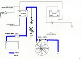
If you are good with electrical stuff (90% of the people here aren't), build your own controller. The numbers on the diagram (#86, #87, etc) refer to the numbers on the bottom of a typical automotive relay.

attachment.php


Note that the thermostat switch in the diagram isn’t really suited for the job. You’ll have to do a Google search and find your own.

This version of the fan controller will continue to run the fan after the ignition switch is turned off, just like most new cars.

To allow the ignition switch to control the fan so that it does not run when the ignition is off, connect the relay contact #86 to the red/green wire on the ignition coil or to the red/yellow wire on the coolant level sensor.

attachment.php


If you are an experienced electronics tech or electrical engineer, email me and I will send you the prototype drawings of a fan controller that is probably as good as the DC Control unit. It is a build it, troubleshoot it yourself item. I will not build or troubleshoot units, so it is not suitable for anyone who isn't really good with electronics.

Alternate placement for a temp gauge sender or temp switch/temp sensor for an electric fan. Use the heater feed that comes off the intake manifold. Cut the rubber hose that connects the manifold water feed to the heater and splice in a tee adapter for the temp gauge sender. Be sure to use the same water feed line as the ECT sensor. That way you will get the most accurate temp readings.

Tee adapter info:
Make a pilgrimage to your local hardware or home supply center and get some copper pipe and a tee that fits the temp gauge sender. Solder two pieces of copper pipe onto a copper pipe tee with threads in the tee part. Find the correct brass fitting to match the temp sender threads to the tee fitting.

attachment.php
 
LiquidGT: Cuz my fan will be on all the time. I'ld rather have a light come on. If my fan isn't working... Like a warning light!

jrichker: Ya I'm doing the 3g alt. swap the same time I'm doing the ele. fan swap. I'm actually using your wiring diagram. For my install. You had posted it in my other thread that I had. Thanx.

So, How does my wiring size sound? Will it be fine for constant usage?

Thanx for the help guys!