Fuel Pump Troubleshooting for 94-95 GT 5.0 Mustangs
Revised 29-Sep-2014 to add diagrams for CCRM and under hood fuse boxes.
Clue – listen for the fuel pump to prime when you first turn the ignition switch on. It should run for 1-5 seconds and shut off. To trick the fuel pump into running, find the ECC test connector and jump the connector in the lower LH corner to ground.
If the relay & inertia switch are OK, you will have power to the pump. Check fuel pressure – remove the cap from the Schrader valve behind the alternator and depress the core. Fuel should squirt out, catch it in a rag. A tire pressure gauge can also be used if you have one - look for 37-40 PSI. Beware of fire hazard when you do this.
No fuel pressure, possible failed items in order of their probability:
A.) Tripped inertia switch – press reset button on the inertia switch. The hatch cars hide it under the plastic trim covering the driver's side taillight. Use the voltmeter or test light to make sure you have power to both sides of the switch
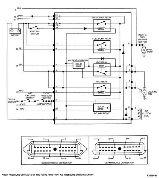
B.) Fuel pump power relay –Note that all the relays on 94-95 models are in the CCRM box under the hood
C.) Clogged fuel filter
D.) Failed fuel pump
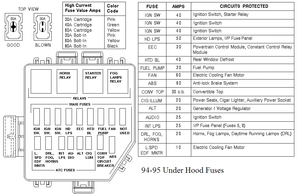
E.) Blown fuse in under hood fuse box.
F.) Fuel pressure regulator failed. Remove vacuum line from regulator and inspect for fuel escaping while pump is running.
The electrical circuit for the fuel pump has two paths, a control path and a power path.
Diagram courtesy of Tmoss & Stang&2birds
The control path consists of the computer, and the fuel pump relay coil. It turns the fuel pump relay on or off under computer control. The switched power (red wire) from the ECC relay goes to the relay coil and then from the relay coil to the computer (light blue\orange wire). The computer provides the ground path to complete the circuit. This ground causes the relay coil to energize and close the contacts for the power path. Keep in mind that you can have voltage to all the right places, but the computer must provide a ground. If there is no ground, the relay will not close the power contacts.
The power path picks up from the under hood fuse box located between the windshield washer filler and the driver's side shock absorber strut tower.. The feed wire from the fuse (pink/black wire) goes to the fuel pump relay contacts. The fuel pump relay is located in the CCRM box on the passenger side of the car up near the radiator. When the contacts close because the relay energizes, the power flows through the pink/black wire to the contacts and through the dark green\yellow wire to the inertia switch. The other side of the inertia switch with the brown\pink wire joins the pink/black wire that connects to the fuel pump. The fuel pump has a black wire that supplies the ground to complete the circuit.
Remember that the computer does not source any power to actuators, relays or injectors, but provides the ground necessary to complete the circuit. That means one side of the circuit will always be hot, and the other side will go to ground or below 1 volt as the computer switches on that circuit.
See
http://www.autozone.com/servlet/UiB..._us/0900823d/80/1d/db/3c/0900823d801ddb3c.jsp for more wiring help for 94-95 cars
Now that you have the theory of how it works, it’s time to go digging.
Power circuits:
Under hood Fuses
Diagram courtesy of Tmoss & Stang&2birds
Click on diagram to enlarge it
CCRM relays - all CCRM relays are located under the hood
CCRM location
Diagram courtesy of http://ww2.justanswer.com
Click on diagram to enlarge it
CCRM Diagram
Diagram courtesy of http://diagrams.hissind.com/
Power feed: Look for 12 volts at the pink/black wire (power source for fuel pump relay). No voltage or low voltage, bad fuse link, bad wiring, or connections.
Relay: Turn on the key and jumper the ECC test connector as previously described. Look for 12 volts at the dark green\yellow wire (relay controlled power for the fuel pump). No voltage there means that the relay has failed, or there is a broken wire in the relay control circuit.
Inertia switch: Check the brown/pink wire, it should have 12 volts. No 12 volts there, either the inertia switch is open or has no power to it. Check both sides of the inertia switch: there should be power on the dark green\yellow (inertia switch input) and brown/pink wire (inertia switch output). Power on the dark green\yellow wire and not on the brown/pink wire means the inertia switch is open. Press on the red plunger to reset it to the closed position. Sometimes the inertia switch will be intermittent or will not pass full power. Be sure that there is 12 volts on both sides of the switch with the pump running and that the voltage drop measured across the switch is less than .75 volts.
Pump wiring: Anytime the ignition switch is in the Run position and the test point is jumpered to ground, there should be at least 12 volts present on the black/pink wire. With power off, check the pump ground: you should see less than 1 ohm between the black wire and chassis ground.
Make sure that the power is off the circuit before making any resistance checks.
If the circuit is powered up, your resistance measurements will be inaccurate.
Fuel tank wiring connector
Control circuits:
Relay: The red wire for the fuel pump relay coil gets its power feed from the ECC relay. No 12 volts here, and the ECC relay has failed or there is bad wiring or bad connections coming from it. The ECC relay is located on top of the computer, which is under the passenger’s side kick panel. It is not easy to get to, you must have small hands or pull the passenger side dash speaker out to access it.
Relay: The light blue/orange wire provides a ground path for the relay power. With the test connector jumpered according to the previous instructions, there should be less than .75 volts. Use a test lamp with one side connected to battery power and the other side to the light blue/orange wire on the fuel pump relay. The test light should glow brightly. No glow and you have a broken wire or bad connection between the test connector and the relay. To test the wiring from the computer, remove the passenger side kick panel and disconnect the computer connector. It has a 10 MM bolt that holds it in place. Remove the test jumper from the ECC test connector. With the test lamp connected to power, jumper pin 22 to ground and the test lamp should glow. No glow and the wiring between the computer and the fuel pump relay is bad.
Computer: If you got this far and everything else checked out good, the computer is suspect .Remove the test jumper from the ECC test connector located under the hood . Remove the plastic cover over the computer wiring, but leave the computer wiring connector plugged into the computer. With the ignition switch in the run position, connect a test lamp to the battery and back probe pin 22, the light blue/orange wire with it. The lamp should glow brightly. No glow and the computer has died a sad death.

If you used a voltmeter instead of a test lamp, you should see less than 1 volt.
See the following website for some help from Tmoss (diagram designer) & Stang&2Birds (website host) for help on 88-95 wiring
http://www.veryuseful.com/mustang/tech/engine/ Everyone should bookmark this site.