Code 14 - Ignition pickup (PIP) was erratic – the hall effect sensor in the distributor is failing. Bad sensor, bad wiring, dirty contacts.
Revised 10-Dec-2012 to add PIP diagnostic testing & Wells info
The PIP is a Hall Effect magnetic sensor that triggers the TFI and injectors. There is a shutter wheel alternately covers and uncovers a fixed magnet as it rotates. The change in the magnetic field triggers the sensor.
They are often heat sensitive, increasing the failure rate as the temperature increases.
PIP Sensor functionality, testing and replacement:
The PIP is a Hall Effect magnetic sensor that triggers the TFI and injectors. There is a shutter wheel alternately covers and uncovers a fixed magnet as it rotates. The change in the magnetic field triggers the sensor. A failing PIP sensor will often set code 14 in the computer. They are often heat sensitive, increasing the failure rate as the temperature increases.
Some simple checks to do
before replacing the PIP sensor or distributor:
You will need a Multimeter or DVM with good batteries: test or replace them before you get started.. You may also need some extra 16-18 gauge wire to extend the length of the meter’s test leads.
Visual check first: look for chaffed or damaged wiring and loose connector pins in the TFI harness connector.
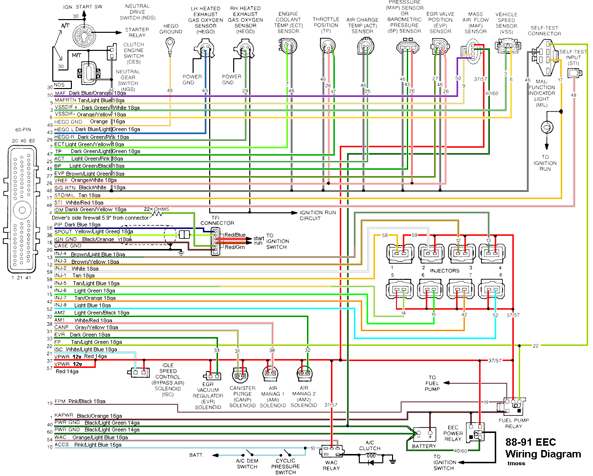
Check the IDM wiring – dark green/yellow wire from the TFI module to pin 4 on the computer. There is a 22K Ohm resistor in the wiring between the TFI and the computer. Use an ohmmeter to measure the wire resistance from the TFI to the computer. You should see 22,000 ohms +/- 10%.
Check the PIP wiring - dark blue from the TFI module to pin 56 on the computer. Use an ohmmeter to measure the wire resistance from the TFI to the computer. You should see 0.2-1.5 ohms.
Check the SPOUT wiring – yellow/lt green from the TFI module to pin 36 on the computer. Use an ohmmeter to measure the wire resistance from the TFI to the computer. You should see 0.2-1.5 ohms.
Check the black/orange wire from the TFI module to pin 16 on the computer. Use an ohmmeter to measure the wire resistance from the TFI to the computer. You should see 0.2-1.5 ohms.
Check the red/green wire; it should have a steady 12-13 volts with the ignition switch on and the engine not running.
Check the red/blue wire; it should have a steady 12-13 volts with the ignition switch in Start and the engine not running. Watch out for the fan blades when you do this test, since the engine will be cranking.
If you do not find any chaffed or broken wires, high resistance connections or loose pins in the wiring harness, replace the PIP sensor or the distributor.
The PIP sensor is mounted in the bottom of the distributor under the shutter wheel. In stock Ford distributors, you have to press the gear off the distributor shaft to get access to it to replace it. Most guys just end up replacing the distributor with a reman unit for about $75 exchange
It is not uncommon to get a defective PIP sensor in a remanufactured distributor.
PIP problems & diagnostic info
Spark with the SPOUT out, but not with the SPOUT in suggests a PIP problem. The PIP signal level needs to be above 6.5 volts to trigger the computer, but only needs to be 5.75 volts to trigger the TFI module. Hence with a weak PIP signal, you could get spark but no injector pulse. You will need an oscilloscope or graphing DVM to measure the output voltage since it is not a straight DC voltage.
See http://www.wellsmfgcorp.com/pdf/counterp_v8_i2_2004.pdf and http://www.wellsmfgcorp.com/pdf/counterp_v8_i3_2004.pdf for verification of this little detail from Wells, a manufacturer of TFI modules and ignition system products.
Code 18 - SPOUT out or wiring fault - look for short to ground in SPOUT wiring going
back to the computer. Possible bad TFI or defective 22 K resistor in the IDM wiring
This code can disable spark advance and reduce power and fuel economy.
Remove the passenger side kick panel and disconnect the computer connector.
There is a 10 MM bolt that holds it in place.
Disconnect the TFI module connector from the TFI and the measure the resistance between the yellow/lt green wire and ground.
You should see greater than 100 K (100000) ohms.
Check the resistance from Pin 4 on the computer connector (dark green/yellow) and the dark green/yellow wire on the TFI connector. You should see 20-24 K Ohms (20,000-24,0000 ohms). The resistor is located in the wiring harness about 6” from the connector. You will need solder and heat shrink to replace the resistor if it is bad.
Next measure the resistance between the yellow/lt green wire on the TFI module connector and
Pin 36 on the computer connector. With the SPOUT plug in place, you should see less than 2 ohms.
The following is a view from the computer side of the computer connector.
This diagram is the wire side of the computer connector.
Diagram courtesy of Tmoss & Stang&2birds
Putting the distributor back in and setting the timing.
You can forget about anything beyond this point if you don't have access to a timing light. You will never get the timing set right without one.
Putting the distributor back in is fairly simple. Pull #1 sparkplug, put your finger in the sparkplug hole, crank the engine until you feel compression. Then line up the TDC mark on the balancer with the pointer on the engine block.
The distributor starts out with the #1 plug wire lined up at about 12:00 with you facing it. Align the rotor to about 11:00, since it will turn clockwise as it slides into place.
Align the distributor rotor up with the #1 position marked on the cap, slide the distributor down into the block, (you may have to wiggle the rotor slightly to get the gear to engage) and then note where the rotor is pointing.
If it still lines up with #1 position on the cap, install the clamp and bolt. If not, pull it out and turn 1 tooth forwards or backwards and try again. Put the #1 spark plug back in and tighten it down, put the clamp on the distributor, but don't tighten it too much, as you will have to move the distributor to set the timing.
Note that there is no such thing as one tooth off on a 5.0 Mustang. If it doesn't align perfectly with #1 position, you can turn the distributor until it does. The only problem is that if you are too far one way or the other, you can't turn the distributor enough to get the 10-14 degree optimum timing range.
Setting the timing:
Paint the mark on the harmonic balancer with paint -choose 10 degrees BTC or 14 degrees BTC or something else if you have NO2 or other power adder. I try to paint TDC red, 10 degrees BTC white and 14 degrees BTC blue.
10 degrees BTC is towards the drivers side marks.
Note: setting the timing beyond the 10 degree mark will give you a little more low speed acceleration.
BUT you will need to run 93 octane to avoid pinging and engine damage. Pinging is very hard to hear at full throttle, so it could be present and you would not hear it.
Simplified diagram of what it looks like. Not all the marks are shown for ease of viewing.
ATC ' ' ' ' ' ' ' ' ' '!' ' ' ' ' ' ' ' ' ' BTC
---------------- >
Direction of Rotation as viewed standing in front of the engine.
The ' is 2 degrees.
The ! is TDC
The
' is 10 degrees BTC
Set the timing 5 marks BTC. Or if you prefer, 5 marks towards the driver's side to get 10 degrees.
To get 14 degrees, set it 7 marks BTC. Or if you prefer, 7 marks towards the driver's side to get 14 degrees.
The paint marks you make are your friends if you do it correctly. They are much easier to see that the marks machined into the harmonic balancer hub.
At this point hook up all the wires, get out the timing light. Connect timing light up to battery & #1 spark plug. Then start the engine.
Remove the SPOUT connector (do a search if you want a picture of the SPOUT connector) It is the 2 pin rectangular plug on the distributor wiring harness. Only the EFI Mustang engines have a SPOUT. If yours is not EFI, check for a SPOUT: if you don’t find one, skip any instructions regarding the SPOUT
Warning: there are only two places the SPOUT should be when you time the engine. The first place is in your pocket while you are setting the timing and the second is back in the harness when you finish. The little bugger is too easy to lose and too hard to find a replacement.
Start engine, loosen distributor hold down with a 1/2" universal socket. Shine the timing light on the marks and turn the distributor until the mark lines up with the edge of the timing pointer. Tighten down the distributor hold down bolt, Replace the SPOUT connector and you are done.
The HO firing order is 1-3-7-2-6-5-4-8.
Non HO firing order is 1-5-4-2-6-3-7-8


 At first I thought it was going to be a pass-through on the left bay, which is something I always thought was cool. I can see spending many hours out there. Nice job