The cutch is suppoes to be pushed in when you dump the codes.
Code 67 - clutch not depressed (5 speed) or car not in neutral or park (auto) or A/C in On position when codes
where dumped. Possible neutral safety switch or wiring problem. This code may prevent you from running the Key On
Engine On tests. You can generally ignore this code, since it has no effect on engine performance.
The computer wants to make sure the A/C is off due to the added load on the engine for the engine running tests. It also
checks to see that the transmission is in Neutral or the clutch depressed (T5, T56, Tremec 3550 & TKO). This prevents
the diagnostics from being run when the car is driven. Key On Engine Running test mode takes the throttle control away
from the driver for several tests. This could prove hazardous if the computer was jumpered into test mode and then driven.
The NSS code 67 can be bypassed for testing. You will need to temporarily ground computer pin 30 to the chassis.
Computer pin 30 uses a Lt blue/yellow wire. Remove the passenger side kick panel and then remove the plastic cover from
the computer wiring connector. Use a safety pin to probe the connector from the rear. Jumper the safety pin to the
ground near the computer.
IF YOU JUMPER THE WIRING TO BYPASS THE NSS, BE SURE TO REMOVE IT PRIOR TO DRIVING THE CAR!!! YOU COULD END UP CRASHING AND BURNING!!!
A search would have unearthed this gem...
See the "
Surging Idle Checklist for help with all your idle/stall problems. Everything you need to find and fix idle problems is in there.
The
first two posts contain all the updates to the fixes. At last count there were
24 possible causes and fixes for surging idle/stall problems. I continue to update it as more people post fixes or ask questions.
Backup lights troubleshooting
Don’t assume that both bulbs can’t be burned. Out. Check both of them
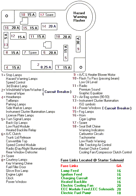
Then check the fuse...
Diagram courtesy of Tmoss & Stang&2birds
Then check the backup switch...
The Tremec 3550 puts the switch in the same location as the T5.
The backup switch wiring connector has 2 contacts that push on the 2 studs that stick out of the top of the switch.
The power side of the connector will be 12 volts anytime the ignition switch is in the Run position. No 12 volts and you have problems with a fuse or the wiring
The lights side will be 12 volts when the ignition switch is in the Run position and the transmission is in reverse. No 12 volts on the lights side and the switch is bad
See the following website for some help from Tmoss (diagram designer) & Stang&2Birds (website host) for help on 88-95 wiring
Mustang FAQ - Engine Information Everyone should bookmark this site.
Ignition switch wiring
http://www.veryuseful.com/mustang/tech/engine/images/IgnitionSwitchWiring.gif
Fuel, alternator, A/C and ignition wiring
http://www.veryuseful.com/mustang/tech/engine/images/fuel-alt-links-ign-ac.gif
Complete computer, actuator & sensor wiring diagram for 88-91 Mass Air Mustangs
http://www.veryuseful.com/mustang/tech/engine/images/88-91_5.0_EEC_Wiring_Diagram.gif
Vacuum diagram 89-93 Mustangs
http://www.veryuseful.com/mustang/tech/engine/images/mustangFoxFordVacuumDiagram.jpg
HVAC vacuum diagram
http://www.veryuseful.com/mustang/tech/engine/images/Mustang_AC_heat_vacuum_controls.gif
TFI module differences & pinout
http://www.veryuseful.com/mustang/tech/engine/images/TFI_5.0_comparison.gif
Fuse box layout
http://www.veryuseful.com/mustang/tech/engine/images/MustangFuseBox.gif