**UPDATED**jrichker where are ya? Need some ALTERNATOR help over here someone
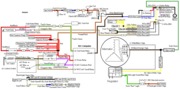
I'm looking for the alternator guru for some diagnostic help. I installed the 3G on my 1990 GT. I used the stock pigtail and harness from a 1994 GT that was a donner car. The car is a basic as they come, the only acessory Im running is the alternator. The entire EFI harness was stripped out before I got it. I installed a battery in the rear the 0 gauge Taylor power wire running from the starter solenoid back to the battery. My MSD box, and electric fan along with the one 2gauge black and orange wire that goes to the 2 grey and then ring terminal from the alternator are all hooked to the battery side of the starter solenoid. The yellow wire is the 20 amp fuse power to the alternator also running to this location. The LG/RD wire I wired directly to the charging circuit keyed hot from the instrument cluster. I have a thick ground cable going from the lower subframe to the motor mount bolt. Everything with MY wiring seems just like it should be and wired just like the factory and Alldata diagram, and looks OEM with loom and all. My problem is that the bastard isnt charging. I have been building this car for 2 years so the only test driving Ive done has been in the past 2 days in my neighborhood. At first the ALT seemed like it was charging just only at 2,000 rpm or higher, which I know can be typical for a under drive pulley like I have on my setup. Well now it's not coming off 12 Volts from my autometer gauge, and I even tested for the needed 14V with a DVOM at the starter solenoid battery cable and still got 12 V. The altenator I recently rebuilt using my painted and clear coated case and new internals from a donnor alternator. I have rebuilt them before so I know what Im doing but is it possible this bitch is already bad or do I have something backwards?????????? WTF someone help I want to drive.......
I'm looking for the alternator guru for some diagnostic help. I installed the 3G on my 1990 GT. I used the stock pigtail and harness from a 1994 GT that was a donner car. The car is a basic as they come, the only acessory Im running is the alternator. The entire EFI harness was stripped out before I got it. I installed a battery in the rear the 0 gauge Taylor power wire running from the starter solenoid back to the battery. My MSD box, and electric fan along with the one 2gauge black and orange wire that goes to the 2 grey and then ring terminal from the alternator are all hooked to the battery side of the starter solenoid. The yellow wire is the 20 amp fuse power to the alternator also running to this location. The LG/RD wire I wired directly to the charging circuit keyed hot from the instrument cluster. I have a thick ground cable going from the lower subframe to the motor mount bolt. Everything with MY wiring seems just like it should be and wired just like the factory and Alldata diagram, and looks OEM with loom and all. My problem is that the bastard isnt charging.