Just orderd the rest of the componets for my shortblock

Any way you slice it, that's still a stock block. I'd be willing to try for 500 rwhp on a stock block. If I was trying for 600 rwhp, I'd be holding my breath when it was on the dyno.

ninety1 5.0 & 5spdGT, if the 70mm TB would've made a difference n/a it would've made an even bigger difference with forced induction. In this case, I think the guy will be fine with a 70mm. I'm sure 5spd could tell us what they flow, and I'll bet that it's substantially more than the heads being used. The point I'm making though is that forced induction isn't some magical quality that eliminate issues with restrictive parts. Just think about it like this: if the atmosphere on earth were 24.7 psi instead of 14.7 psi, would the ______ still be the most restrictive part?

I know that some subtle things are different, like optimized cams that prevent reversion of the airflow, and apparently harmonics and pressure waves act differently, but basic fluid dynamics remains the same. If a throttle body/intake/head is costing you 10hp at 1 bar, it'll cost you 20 at 2 bar.

Last, I think this guy is going to make a massive amount of power. With the cam, the intake, and the heads he's got, he should be well over 350 rwhp n/a and with 10 psi on top, he's going to be looking at 500+ rwhp.... Just a guess, though.

Chris
 
ninety1 5.0 & 5spdGT, if the 70mm TB would've made a difference n/a it would've made an even bigger difference with forced induction. In this case, I think the guy will be fine with a 70mm. I'm sure 5spd could tell us what they flow, and I'll bet that it's substantially more than the heads being used. The point I'm making though is that forced induction isn't some magical quality that eliminate issues with restrictive parts. Just think about it like this: if the atmosphere on earth were 24.7 psi instead of 14.7 psi, would the ______ still be the most restrictive part?

I know that some subtle things are different, like optimized cams that prevent reversion of the airflow, and apparently harmonics and pressure waves act differently, but basic fluid dynamics remains the same. If a throttle body/intake/head is costing you 10hp at 1 bar, it'll cost you 20 at 2 bar.

Yes, you are correct. Less restrictive parts will help and the supercharger will not cancel out restrictive parts.

However, the 75mm TB would flow more than the intake can, because the Holley intake necks down to near 65mm anyway. So as I stated, the 70mm is not going to be a problem at all.

When most speak of "throttle body matching" they are referring to just the inlet, but do not go inches into the intake. What is the point of a 75mm TB when a couple inches in, it goes down to 65mm. At that point, the throttle body is not the restriction.

I do not see the throttle body being a restriction here, but I see your point and have actually posted on that on several occasions in the past:nice:

Yep, I got the flow rates at 28":)

Throttle Body CFM Flow Ratings:

Stock 5.0L 60 MM - 526 CFM
SVO 65 MM - 540 CFM

Accufab:

65 MM - 664 CFM
70 MM - 787 CFM
70 MM - 896 CFM (Race version)
75 MM - 924 CFM
75 MM - 1045 CFM (Race version)
80 MM - 1142 CFM
85 MM - 1322 CFM
90 MM - 1369 CFM
105 MM - 1550 CFM

Holley:

65 MM - 750 CFM*
70 MM - 790 CFM*
75 MM - 840 CFM*
80 MM - 892 CFM*

*Information given by Tech Rep.

BBK:

70 MM - 726 CFM

Edelbrock, Ford Racing and Proffessional Products have no cfm information after calls/emails.

Information to keep in mind when picking out a throttle body for your application:

A 300 cubic inch engine (302 c.i.) flows 521 cfm at 6,000 rpm.
A 330 cubic inch engine (331 c.i.) flows 573 cfm at 6,000 rpm.
A 350 cubic inch engine (347 c.i.) flows 600 cfm at 6,000 rpm.

With the above information from Accufab's website, you can see that the aftermarket throttle bodies offered flow much more than your engine can breath (302-347). Those cfm ratings are even given with NO restrictions and of course our engines all have restrictions, via our heads, cam, intake packaging. An actual running engine flows somewhere in the neighborhood of 200-400 cfm with some rough math. The aftermarket throttle bodies flow two times this amount.

In short, be careful on picking 'too big' of a throttle body for your car. An application with boost (forcing air) allows for you to efficienty select a bigger throttle body, although N/A engines do not.

If you've got a throttle body that delivers 100% of the peak air requirements of your engine when the throttle plate is fully open, you have control of the air throughout 100% of the throttle position range. If you go to an oversized TB that delivers 100% of the air that your engine can consume while the throttle plate is only 60% open, you have given up usable throttle-control range for no advantage.
 
he sold just the heads and intake??? im pretty sure dss blocks come with the main support system installed... the crank i dunno ,,whats the compression on it to??? cuz u said your gonna supercharge it......


yup i know its a shame. but the heads were smaller and the compression was higher then. I ordered the next size up 185's and i got the cnc ports done to them. (they claim another 30-40hp). The motor was originally around 10.3-1. compression with the larger chamber size heads and the cnc ports it should be around 9.8-1.
 
5spd,

Good write-up. You and I see eye to eye on this particular issue. I'd like to turn your concentration now to a couple of conceptual ideas.

If given the choice, I would always take the TB that minimizes the turbulence of the air as it transitions into the intake's port. More preferably, I would match the port to the TB. A smaller TB will create turbulence even though the intake "necks" down.

Also, keep in mind that the numbers you get for cfm of an engine do not necessarily correlate to that of the TBs airflow. The TBs were tested at a constant pressure of 28". In a running engine, it's not exactly the same. Atmospheric pressue at sea level under normal conditions is 29.92". Also, the pressure differential between the atmosphere, the intake tract, and inside the intake differs from engine to engine based on their components. What is comparable though, is how the throttle body flows at 28" vs. how the intake, or the heads flow at 28". Then you can see which is the weakest link.

Why do you say that an actual running engine draws 200-400 cfm? I assume you're talking about throughout the rpm range. Keep in mind that while average volumetric efficiency is in the 75% range, these mild combinations that gearheads put together can be in the 85-90% range. The wild combos can even exceed 100% v.e.

Last, and this point is related to the earlier one, you can't assume that a boosted engine will need a bigger throttle body than the same engine naturally aspirated. The fact that a higher pressure is introduced on the outside of the TB means that it will flow more air, in volume, than it did at atmospheric conditions. Twice the pressure means twice the air. Another, way to look at it is that the air moving through the TB is denser because pressure is higher so that while the same volume/ unit time is entering the engine, there is an increase in air mass/ unit time.

That's probably a more accurate way to look at it because whether n/a or under 100 psi of boost, the 302 engine is still going to displace 302 c.i., which means that at a given rpm it will move the exact same volume of air into the cylinder during each stroke regardless of the boost pressure. (For conceptual purposes assume away the turbo's effect on wave theory and resonance etc...)

I'm not the most articulate person in the world. Hopefully, you understand what I'm trying to say.

Chris
 
5spd,

Good write-up. You and I see eye to eye on this particular issue. I'd like to turn your concentration now to a couple of conceptual ideas.

If given the choice, I would always take the TB that minimizes the turbulence of the air as it transitions into the intake's port. More preferably, I would match the port to the TB. A smaller TB will create turbulence even though the intake "necks" down.

Also, keep in mind that the numbers you get for cfm of an engine do not necessarily correlate to that of the TBs airflow. The TBs were tested at a constant pressure of 28". In a running engine, it's not exactly the same. Atmospheric pressue at sea level under normal conditions is 29.92". Also, the pressure differential between the atmosphere, the intake tract, and inside the intake differs from engine to engine based on their components. What is comparable though, is how the throttle body flows at 28" vs. how the intake, or the heads flow at 28". Then you can see which is the weakest link.

Why do you say that an actual running engine draws 200-400 cfm? I assume you're talking about throughout the rpm range. Keep in mind that while average volumetric efficiency is in the 75% range, these mild combinations that gearheads put together can be in the 85-90% range. The wild combos can even exceed 100% v.e.

Last, and this point is related to the earlier one, you can't assume that a boosted engine will need a bigger throttle body than the same engine naturally aspirated. The fact that a higher pressure is introduced on the outside of the TB means that it will flow more air, in volume, than it did at atmospheric conditions. Twice the pressure means twice the air. Another, way to look at it is that the air moving through the TB is denser because pressure is higher so that while the same volume/ unit time is entering the engine, there is an increase in air mass/ unit time.

That's probably a more accurate way to look at it because whether n/a or under 100 psi of boost, the 302 engine is still going to displace 302 c.i., which means that at a given rpm it will move the exact same volume of air into the cylinder during each stroke regardless of the boost pressure. (For conceptual purposes assume away the turbo's effect on wave theory and resonance etc...)

I'm not the most articulate person in the world. Hopefully, you understand what I'm trying to say.

Chris

I understand what you are saying, and it all looks good to me!

I posted the 28" numbers as a fact of keeping everything on an even playing field. Head flow, intake flow, throttle body flow, etc. I think you understood that, because you stated it.

I believe oversizing the throttle body could cause some turbulence issues as well. Putting a 90mm TB on an original opening of 70mm, but just opening up the inlet on the surface, is only allowing all that air to come down steeply in the intake tract to the "neck down" as I like to call it, which I believe could cause some unnecessary turbulence.

Undersizing could also cause an issue as well, but in these cases, I believe it would be unseen, much like that of oversizing. Having to small of a throttle body, like a 65 on a 90mm opening, I could see causing some pressure drop, and therefore turbulence.

My point is, that I believe matching the throttle body to the intake is fine, but I see in 90+% of the cases, that going with a suggested larger throttle body is not needed.

I have yet to see any definite proof on how the large throttle body guys have seen gains. There are just to many variable changes on the "proof examples."

My 200-400 cfm depends on what top-end parts where used, in correlation to the camshaft as well. The engine is not "free"...:)

A throttle body is actually pretty important an engine, because that is how we regulate the amount of air we want into the engine. Without a throttle body, it would be one big vacuum leak:)
 
Have you seen the new kickass infinitely variable valvetrains they're coming out with, now? That is some neat stuff. No throttle body necessary. They just increase and decrease lift and displacement. I forget who's developing engines with this technology.

Turbo guys are constantly working with volumetric efficiency to figure out the right size turbos to put on engines. Basically all you have to do to figure out actual flow of a motor is multiply the ideal flow at 100% VE by the actual VE of that motor.

Equation should look something like this:

displacement * rpm * VE / (1728*2) = Volumetric flow of the engine in CFM

the 1728 converts from in^3 to ft^3, and the 2 comes from dividing rpm by 2 in order to get the actual number of intake strokes.

VE is, like you said, determined by the top-end motor components and the cam.

Do you know how to read compressor maps?

Chris
 
Have you seen the new kickass infinitely variable valvetrains they're coming out with, now? That is some neat stuff. No throttle body necessary. They just increase and decrease lift and displacement. I forget who's developing engines with this technology.

Turbo guys are constantly working with volumetric efficiency to figure out the right size turbos to put on engines. Basically all you have to do to figure out actual flow of a motor is multiply the ideal flow at 100% VE by the actual VE of that motor.

Equation should look something like this:

displacement * rpm * VE / (1728*2) = Volumetric flow of the engine in CFM

the 1728 converts from in^3 to ft^3, and the 2 comes from dividing rpm by 2 in order to get the actual number of intake strokes.

VE is, like you said, determined by the top-end motor components and the cam.

Do you know how to read compressor maps?

Chris

Yeah, I am familiar with the volumetric efficiency calculations:nice: As you know, getting the air in (top-end) and getting it out (exhaust) the most efficient way is always best for VE. You created a thread about it not to long ago, and I supplied some answers I got from some physics forums that I frequent. Your post were right in line...

I have never looked at compressor maps before, but I have heard the reference used on a couple of occasions. If I recall, it is dealing with the atmospheric pressure (that you talked about later) coupled with boost psi, or something to that effect.

You are one of the top guys I trust with unbias information on this site. I would not mind learning a thing or two, or atleast get the idea.
 
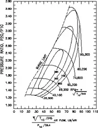
The entire point to reading a compressor map is to determine which turbo or turbos, if you're going twin, are right for your engine.

Well, the reason I brought up the VE formula first is because it is a necessary component that you need to solve for before you start analyzing turbos. There are two peices of information you must know to read one. The first is the pressure you intend to run. As you can see in the examples below, pressure is listed in "bar" on the y-axis. bar is 1 atmosphere at sea level 1 bar = 14.7 psi = 29.92 in Hg. 1 is the baseline. Any boost you add is in addition to 1 bar. So, for example, if you run 14.7 psi, you would find 2 bar on the y-axis.

The second bit of info that you need to interpret the compressor map is the air mass that your engine will be moving. with the VE formula, you already know how to determine what an engine will flow at a given rpm. You'll usually have to guess at it's actual VE unless you can determine a way to test it... But on a stock engine a VE of 75% is common. A mild street build would probably put you in the 85% range, the AFR combo that we did with our 302s I would roughly guesstimate about 90%.

This is probably not the best way to estimate VE, but I usually look at other combos running their peak hp at the same rpm as mine. I made 311rwhp on the dyno, maybe 320 all said and done. The best I've seen from a 302 at 5500rpm where my hp peak was is maybe 350 rwhp (that's giving my engine a very conservative estimate). There are problems with using this method, like the fact that it doesn't take into account thermal efficiency which would change based on compression ratio, but it's only meant to be a ballpark anyway. Bottom line 311/350 = 88.9% and that's probably a conservative close estimate to the VE of that old 302. On a side not, that gives you an idea of how poor the VE on the stock 5.0 is. Use my method or just guess. Either way, it won't throw your result off enough to confuse which turbo will be right for your combination.

Once you have the volumetric flow of your engine at several rpm points, you convert air volume into air mass. This is necessary because volume of air doesn't take into account how much air the turbo is really moving. The engine is going to digest the same volume regardless, but with increasing boost it will be injesting increasing air mass. You should look up the formula for converting air mass from volume. You basically just multiply the volume by the density of the air. The formula for density incorporates the temp (in Kelvin) of the air in the manifold, the pressure, and the molecular weight of the air. If you don't feel like going through all of that, find an online calculator or excel program that can solve it for you.

Once you have the air mass flow at several different rpm points, you simply chart it, and find where the rpm band falls in the compressor's efficiency islands. Nothing too difficult. I don't have much time right now, so I'll post the examples of compressor maps and will walk you through an example tomorrow.

Chris
 
t61.webp
t76.webp


Sorry I couldn't stick around long to give a better explanation. I'll try to get more time on the computer tomorrow night.

Chris
 

Attachments

  • t61.webp
    t61.webp
    24.3 KB · Views: 122
  • t76.webp
    t76.webp
    16.2 KB · Views: 122
Hey man.... Sorry, I just jumped on to get back to you since I said I would. I apologize for being preoccupied with killing bad guys last night (I'm 8 hours ahead of you). I'll try harder to get online tonight for an explanation and example.

Chris
 
Alright, I’m sorry it took so long for me to get back to you on this. I hate how unpredictable my job is…

So, let’s take, for example, my 331. Lts see how the T76 turbo will do in my rpm band at say 2 bar (14.7psi), which is about the limit of what I can run on pump gas.

We can use the VE formula to determine what it flows at different points throughout the RPM band. The two points I’m most concerned with is the point that I think the given turbo will spool, and the redline or shiftpoint of the motor. Where the turbo will spool is a mystery. I don’t know of any definitive formula or charts to look at that will help you determine that. It depends on the particular engine’s exhaust flow, the size of both wheels, and the turbine’s (exhaust wheel’s) characteristics (A/R, trim, housing size, etc…). The best you can do is look at other people’s combos and try to determine how your combo will compare.

In my particular case, I think my turbo will reach max boost no earlier than 3500 rpm. My redline is 7000 rpm. According to the VE formula, assuming 90% VE, my 331 will flow about 302 cfm before I add boost.

Next, figure out how much air mass (in lbs/min) will be moving into the motor: calculate the boost in bar and multiply that by the “preboosted” cfm to find the equivalent airflow into the engine: 2bar*302cfm = 604 cfm (this is not actually the volumetric flow into the engine, but it’s the equivalent. Now, the final step is to multiply by .07 (a rule of thumb) to get the lbs/min: 604*.07 = 42.28 lbs/ min.

Now simply take a look at the T76 graph and find where 42.28 lbs/min from the x-axis intersects 2bar from the y-axis. Whichever island it falls on is the efficiency level. If you’ve learned calculus or you are familiar with elevation maps, you’ll probably recognize the compressor maps as a 3 dimensional graph. In this case, the T76 graph is hard to read, but the point lands just to the right of the surge-line (landing to the left would be bad). It’s on the second rung of the island and I can’t make it out clearly but it looks like it says 76%.

Now you can do the same math for 7000 rpm, and you should come up with 84.56 (pretty easy since 7000 rpm is double 3500…). So, 84.56 and 2-bar intersect to the right of the efficiency islands, and less than the last rung, which looks like 66% efficiency. From personal experience, that turbo would still make power at that rpm, just less efficiently. Now, we can do the same thing on graphs of other compressors to see how they compare on our engine combination.

Disclaimer: If you go back and confirm the results with a calculator or something, you’ll come close to our estimation – close enough to derive good results from the compressor map. Since I rounded the displacement to exactly 331, used the .07 conversion from CFM to lbs/min, and rounded my math, it won’t be exact. Also, it’s conservative because 90% VE is conservative for my engine. If you don’t want to used .07 as a rule of thumb, here’s the correct formula: [(psi of boost + psi of atmosphere) * Volumetric flow * 29]/ (10.73*temperature in Rankine)

Rankine is absolute temperature and is equal to (460 degrees + the temperature in Fahrenheit.) That temp would be the intake air temperature, or the temperature as measured in the intake tract after the intercooler. The correct way to represent the above is:

(psia * V*29)/(10.73 * T)

psia = absolute pressure in psi. This is the sum of atmospheric pressure, and psig where g stands for gauge. The turbo's added boost is psig

Did all of the concepts make sense? Were you able to work it out? If so, you’re a step ahead of 90% of gear-heads in you understanding of how air-flow affect engine dynamics, and you have a good understanding of turbo selection.

Ps. Twin turbos are the same, you just have to divide your lbs/min by 2, because you’re deviding the airflow by two turbos. (essentially, you’re running 4 cylinders per turbo and thus using half as much airflow.)

I think that’s about the best explanation I can provide. If you’d like me to go into detail on anything, I’ll give it a shot.

FWIW, another rule of thumb that is good to know is that for every lb of air flow, your engine will produce ~10.86 hp.
 
Chris, that was extremely informative and is actually fairly easy to comprehend. However, I had to read it a couple times;)

I printed off the sample compressor map for the far right, and it did look like 76%, but it was not entirely clear. I was thinking the inner ring is 78%, 76%, and 70% going outwards:shrug:

Two questions:

1. Is the percentage the turbo efficiency?

2. Is the graph at the highest point, is the top elevation to shoot for, correct?

So you believe that the best points (which makes sense!) is the potential spool up point and the shift rpm VE?

I found this, and they use different percentages it looks like so that did not help me figuring out what the percentage was:

http://www.automotivearticles.com/printer_Turbo_Selection.shtml

Be careful over there...:nice:

I am in no hurry, I will always be on here. I will always remember this thread and refer back to it for help. You provided an easy to follow tutorial, so good job for that.
 
Chris, that was extremely informative and is actually fairly easy to comprehend. However, I had to read it a couple times;)

Sweet! You've got a pretty keen mind for these types of things. It took me a while to grasp everything.

I printed off the sample compressor map for the far right, and it did look like 76%, but it was not entirely clear. I was thinking the inner ring is 78%, 76%, and 70% going outwards:shrug:

Two questions:

1. Is the percentage the turbo efficiency?

That's the compressor's efficiency, and it doesn't take into accout the turbine's efficiency (the turbine is the exhaust wheel). As far as efficiency goes, I speculate that means that the turbo is 76% efficient at converting the kinetic energy being transferred from the compressor wheel into the kinetic energy of the air. To get the turbo's efficiency you'd have to find the efficiency of the compressor, the efficiency of the turbine, the efficiency of the transfer of force from the turbine to the compressor, the efficiency of flow through the housings etc... Noone actually does all of that to my knowledge. One of the cool things about turbos as opposed to superchargers, as you've undoubtedly heard, is that they're using otherwise unspent exhaust energy as the source of the energy anyway. So even if the whole turbo is only 50% efficient, that's still taking advantage of energy that wasn't being used before.

2. Is the graph at the highest point, is the top elevation to shoot for, correct?

Yeah, but it's kinda like shooting for the highest peak hp number. What would you rather have, the higher peak number or the highest avg hp through your powerband? I would personally rather have the highest avg hp, and therefore the highest average compressor efficiency through my powerband.

So you believe that the best points (which makes sense!) is the potential spool up point and the shift rpm VE?

You mean compressor efficiency not VE. And, yeah those are the best two points to plot, because then you can just draw a line between them and you'll see how the compressor does from the bottom of your powerband to the top. That goes back to the last point I made above. I would personally be shooting for the highest average compressor efficiency throughout the powerband.

I found this, and they use different percentages it looks like so that did not help me figuring out what the percentage was:

http://www.automotivearticles.com/printer_Turbo_Selection.shtml

It looks like the author of that article has an elementary knowledge of the physics concepts behind what's going on. They use different percentages because that compressor map represents a different compressor. However, they're still using the same process I just laid out.

The reason I said they're still on the elementary level is because of a couple comments:
Without getting into the thermodynamics of adiabatic heat-pumps, we’ll just say that efficiency is a measure of how much excess heat the turbo puts into the compressed air coming out of the outlet.

It's true that less efficient compressors will have hotter output temps, but efficiency is not "a measure of how much excess heat the turbo puts into the compressed air" It's a measure of the transfer of energy from your input into your intended output: Ein/Eout. The extra energy that isn't used the way you want it to be used is instead turned into heat, sound, vibration, etc...

Another thing that they don't seem to have a solid grasp of is why the turbine housing and wheel are important. This is a little more complex, and would be easier to discuss over the phone if I could do it, but unfortunately I don't have that ability here.

You should try to gain an understanding of A/R, wheel trim, and size and how they affect air-flow etc... I will try to explain all of that next time. Can't stick around too much longer, tonight. There are others who would like to use the only internet connection that we have in the building.

Be careful over there...:nice:
Thanks man :flag: I'm doing my best over here.

I am in no hurry, I will always be on here. I will always remember this thread and refer back to it for help. You provided an easy to follow tutorial, so good job for that.

Thanks man... I'm just passing on the knowledge that others gave to me. You seem to really enjoy conceptualizing things. That's something we have in common.

Chris
 
I want to clarify something that you most likely already understand. Once I know the boost I will run the turbo at, I want to pick the compressor that will yeild the highest avg efficiency. If I run more boost, I'll still make more power, but then I'd prefer a compressor that gave me better efficiency at that boost.
 
Now Chris, I am by no means an expert:) but the way you laid it out makes it easy to comprehend, as compared to other methods of teaching.

I used that link above just to see if the compressor efficiency numbers are the same for every "graph." I actually did not read the article, because I thought your explanation was easier to follow.

I never have looked into boost that much, but this does tickle my fancy a little bit. With some more thinking time, I believe I could understand it even further than I do now of course. However school and some of the activities around it are taking most of my intellectual time right now...

Thanks again and just do what you do:nice:

And yes, average horsepower over the powerband over peak...