

Hey all I have an 89 gt hatchback that I've been dealing with a slight miss and loss of power when warmed up all the way. I ran codes with the equus code reader and pulled up o2 sensors bad, Egr valve not opening, idle out of range, and ect out of range. So far I replaced fuel filter, PCv valve,grommet, filter, plugs cap rotor wires, plugs gapped at. 054, new flow matched injectors, motorcraft Egr and position sensor, base idle set, timing at 14 degrees w spout out and Tps set at .94 v. By all accounts it should run decent right? As soon as the car hits full operating temp it feels like its running at 50% power. I have ect, act, 180 t stat and a gt40 intake I'm putting on this weekend. Could the ect be causing my problems?
You are using an out of date browser. It may not display this or other websites correctly.
You should upgrade or use an alternative browser.
You should upgrade or use an alternative browser.
loss of power when warmed up
- Thread starter 85SVOGUY
- Start date

jcgafford
10 Year Member
My code reader stopped working after it got dropped so I ordered a new one and its coming in tomorrow. The only known problems I know it has, are the stock cats are shot. They rattle like crazy and I know my ect sensor is bad. I haven't checked fuel pressure, cylinder balance test, compression test ect.
jcgafford
10 Year Member
use a paper clip. same results .0001% cost of a code reader. cats won't throw codes, there are no o2 sensors behind them to tell the computer they are bad.My code reader stopped working after it got dropped so I ordered a new one and its coming in tomorrow. The only known problems I know it has, are the stock cats are shot. They rattle like crazy and I know my ect sensor is bad. I haven't checked fuel pressure, cylinder balance test, compression test ect.

Yes, ECT sensor could cause poor running.
BUT, you mentioned you had codes for the O2 sensors, but didn't mention replacing them.
usually when i have a bunch of codes, i erase them all and see what comes back. Seeing as you replaced some parts, the next step would be to clear the codes either by unhooking the battery, or with the reader (for that equuis model, simple press the TEST/HOLD button while the codes are being displayed to erase the Continuous Memory codes)
Then, go for a ride and then run the codes again.
BTW, always make sure the engine is warm when you run the test, or you always get a code 21 for the ECT
BUT, you mentioned you had codes for the O2 sensors, but didn't mention replacing them.
usually when i have a bunch of codes, i erase them all and see what comes back. Seeing as you replaced some parts, the next step would be to clear the codes either by unhooking the battery, or with the reader (for that equuis model, simple press the TEST/HOLD button while the codes are being displayed to erase the Continuous Memory codes)
Then, go for a ride and then run the codes again.
BTW, always make sure the engine is warm when you run the test, or you always get a code 21 for the ECT

jcgafford
10 Year Member
running it till it is at operating temp should get rid of the code 21 and may produce more koer codes. you should be able to run koeo codes anytime you want to.Yes sorry I replaced both o2 sensors with motorcraft units from rockauto. Ill post back with my results. When I ran the tests before it was driven for 25 minutes before the test.
Did my GT40 upper and lower intake swap today. Also changed out the T-stat for an 180, changed ect, and act sensor. Ran the KOEO test and it gave me a code 11 which is all clear. I'm going to run the KOER test when I get a helper because i don't have the extension cable. It seems to be running pretty good. Drove it around for 10 minutes, no backfires, hanging idle etc. We'll see what happens when I drive it longer. i'll be back with the other codes if i get any.
jcgafford
10 Year Member
There is a time delay for koer. You can run it and the balance test by yourself. I have multiple times.
Correction on the earlier post. I did the KOEO test and it came up with code 11, then code 33. I don't understand why I keep getting codes. I changed the EGR Valve with a motorcraft piece brand new from rockauto, and I replaced the EGR Valve position sensor. The only other thing I can think of is the lines maybe? Any input appreciated. I can't run the KOER test because it keeps throwing that continuous 33.

Code 33 - Insufficient EGR flow detected.
Look for vacuum leaks, cracked vacuum lines, failed EGR vacuum regulator. Check to see if you have 10” of vacuum at the EGR vacuum connection coming from the intake manifold. Look for electrical signal at the vacuum regulator solenoid valves located on the rear of the passenger side wheel well. Using a test light across the electrical connector, it should flicker as the electrical signal changes. Remember that the computer does not source any power, but provides the ground necessary to complete the circuit. That means one side of the circuit will always be hot, and the other side will go to ground or below 1 volt as the computer switches on that circuit.
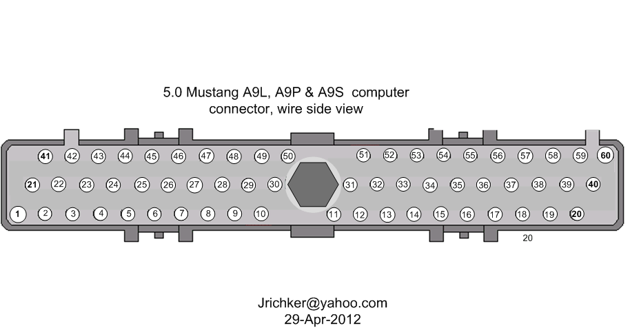
Check for resistance between the brown/lt green wire on the EGR sensor and pin 27 on the computer: you should have less than 1.5 ohm.
Backside view of the computer wiring connector:
See the following website for some help from Tmoss (diagram designer) & Stang&2Birds (website host)
http://www.veryuseful.com/mustang/tech/engine/images/fuel-alt-links-ign-ac.gif
http://www.veryuseful.com/mustang/tech/engine/images/88-91eecPinout.gif
EGR test procedure courtesy of cjones
to check the EGR valve:
bring the engine to normal temp.
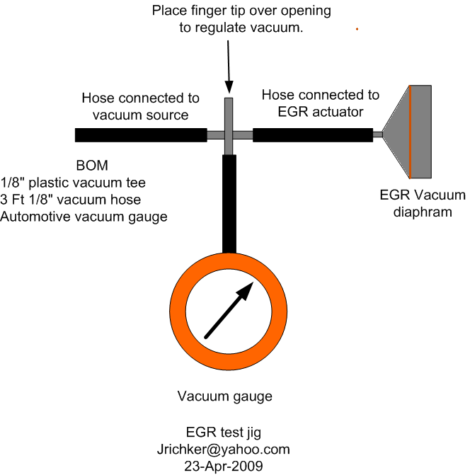
connect a vacuum pump to the EGR Valve or see the EGR test jig drawing below. Connnect the test jig or to directly to manifold vacuum.
Do not connect the EGR test jig to the EVR (Electronic Vacuum Regulator).
apply 5in vacuum to the valve. Using the test jig, use your finger to vary the vacuum
if engine stumbled or died then EGR Valve and passage(there is a passageway through the heads and intake) are good.
if engine did NOT stumble or die then either the EGR Valve is bad and/or the passage is blocked.
if engine stumbled, connect EGR test jig to the hose coming off of the EGR Valve.
Use your finger to cap the open port on the vacuum tee.
snap throttle to 2500 RPM (remember snap the throttle don't hold it there).
did the vacuum gauge show about 2-5 in vacuum?
if not the EVR has failed
EGR test jig
The operation of the EGR vacuum regulator can be checked by using a test light applied across the wiring connector. Jumper the computer into self test mode and turn the key on but do not start the engine. You will hear all the actuators (including the EVR vacuum regulator) cycle. Watch for the light to flicker: that means the computer has signaled the EGR vacuum regulator successfully.
Some basic theory to clarify how things work is in order…
EGR System theory and testing
The EGR shuts off at Wide Open Throttle (WOT), so it has minimal effect on performance. The addition of exhaust gas drops combustion temperature, increases gas mileage and reduces the tendency of the engine to ping. It can also reduce HC emissions by reducing fuel consumption. The primary result of EGR usage is a reduction in NOx emissions.
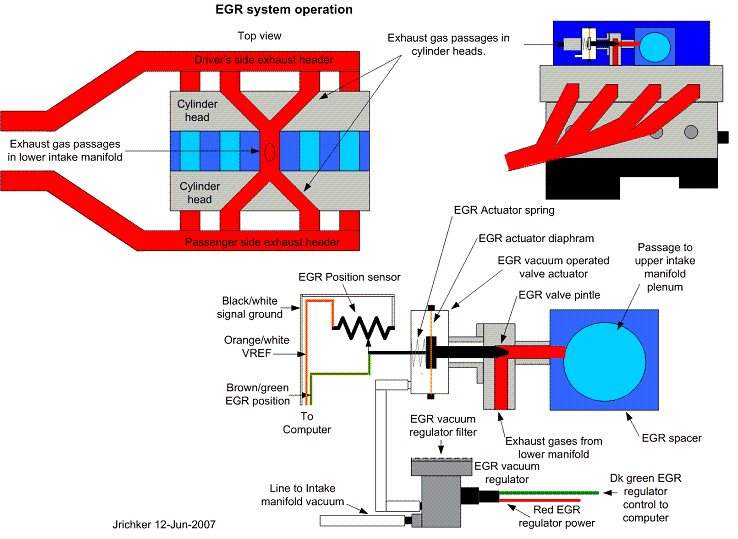
The EGR system has a vacuum source (line from the intake manifold) that goes to the EVR, computer operated electronic vacuum regulator. The EVR is located on the back of the passenger side shock strut tower. The computer uses RPM, Load. and some other factors to tell the EVR to pass vacuum to open the EGR valve. The EGR valve and the passages in the heads and intake manifold route exhaust gas to the EGR spacer (throttle body spacer). The EGR sensor tells the computer how far the EGR valve is open. Then computer adjusts the signal sent to the EVR to hold, increase or decrease the vacuum. The computer adds spark advance to compensate for the recirculated gases and the slower rate they burn at.
Troubleshooting:
There should be no vacuum at the EGR valve when at idle. If there is, the EVR (electronic vacuum regulator) mounted on the backside of the passenger side wheelwell is suspect. Check the vacuum line plumbing to make sure the previous owner didn’t cross the vacuum lines.
Diagram courtesy of Tmoss & Stang&2birds. (the diagram says 88 GT, but the EGR part is the same for 86-93 Mustangs)
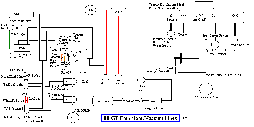
The EGR sensor is basically a variable resistor, like the volume control on a radio. One end is 5 volt VREF power from the computer (red/orange wire). One end is computer signal ground (black/white), and the middle wire (brown/lt green) is the signal output from the EGR sensor. It is designed to always have some small voltage output from it anytime the ignition switch is the Run position. That way the computer knows the sensor & the wiring is OK. No voltage on computer pin 27 (brown/lt green wire) and the computer thinks the sensor is bad or the wire is broken and sets code 31. The voltage output can range from approximately .6-.85 volt.
The EVR regulates vacuum to the EGR valve to maintain the correct amount of vacuum. The solenoid coil should measure 20-70 Ohms resistance. The regulator has a vacuum feed on the bottom which draws from the intake manifold. The other vacuum line is regulated vacuum going to the EGR valve. One side of the EVR electrical circuit is +12 volts anytime the ignition switch is in the run position. The other side of the electrical circuit is the ground path and is controlled by the computer. The computer switches the ground on and off to control the regulator solenoid.
EGR test procedure courtesy of cjones
To check the EGR valve:
Bring the engine to normal temp.
Connect a vacuum pump to the EGR Valve or see the EGR test jig drawing below. Connnect the test jig or to directly to manifold vacuum.
Do not connect the EGR test jig to the EVR (Electronic Vacuum Regulator).
Apply 5in vacuum to the valve. Using the test jig, use your finger to vary the vacuum
If the engine stumbled or died then EGR Valve and passage(there is a passageway through the heads and intake) are good.
If the engine did NOT stumble or die then either the EGR Valve is bad and/or the passage is blocked.
If the engine stumbled, connect EGR test jig to the hose coming off of the EGR Valve.
Use your finger to cap the open port on the vacuum tee.
Snap throttle to 2500 RPM (remember snap the throttle don't hold it there).
Did the vacuum gauge show about 2-5 in vacuum?
If not the EVR has failed
EGR test jig
To test the computer and wiring to the computer, you can use a test light across the EVR wiring connectors and dump the codes. When you dump the codes, the computer does a self test that toggles every relay/actuator/solenoid on and off. When this happens, the test light will flicker. If the test light remains on the computer or the wiring is suspect.
To check the EVR to computer wiring, disconnect the EVR connector and connect one end of the Ohmmeter to the dark green wire EVR wiring. Remove the passenger side kick panel and use a 10 MM socket to remove the computer connector from the computer. Set the Ohmmeter to high range and connect the other ohmmeter lead to ground. You should see an infinite open circuit indication or a reading greater than 1 Meg Ohm. If you see less than 200 Ohms, the dark green wire has shorted to ground somewhere.
Late Model Restoration may still have the Ford Racing M-12071-N302 kit with the EGR valve & sensor along with the ACT & ECT sensors for $45. See http://www.latemodelrestoration.com/iwwida.pvx?;item?item_no=M12071N302 1&comp=LRS for more details
Look for vacuum leaks, cracked vacuum lines, failed EGR vacuum regulator. Check to see if you have 10” of vacuum at the EGR vacuum connection coming from the intake manifold. Look for electrical signal at the vacuum regulator solenoid valves located on the rear of the passenger side wheel well. Using a test light across the electrical connector, it should flicker as the electrical signal changes. Remember that the computer does not source any power, but provides the ground necessary to complete the circuit. That means one side of the circuit will always be hot, and the other side will go to ground or below 1 volt as the computer switches on that circuit.
Check for resistance between the brown/lt green wire on the EGR sensor and pin 27 on the computer: you should have less than 1.5 ohm.
Backside view of the computer wiring connector:
See the following website for some help from Tmoss (diagram designer) & Stang&2Birds (website host)
http://www.veryuseful.com/mustang/tech/engine/images/fuel-alt-links-ign-ac.gif
http://www.veryuseful.com/mustang/tech/engine/images/88-91eecPinout.gif
EGR test procedure courtesy of cjones
to check the EGR valve:
bring the engine to normal temp.
connect a vacuum pump to the EGR Valve or see the EGR test jig drawing below. Connnect the test jig or to directly to manifold vacuum.
Do not connect the EGR test jig to the EVR (Electronic Vacuum Regulator).
apply 5in vacuum to the valve. Using the test jig, use your finger to vary the vacuum
if engine stumbled or died then EGR Valve and passage(there is a passageway through the heads and intake) are good.
if engine did NOT stumble or die then either the EGR Valve is bad and/or the passage is blocked.
if engine stumbled, connect EGR test jig to the hose coming off of the EGR Valve.
Use your finger to cap the open port on the vacuum tee.
snap throttle to 2500 RPM (remember snap the throttle don't hold it there).
did the vacuum gauge show about 2-5 in vacuum?
if not the EVR has failed
EGR test jig
The operation of the EGR vacuum regulator can be checked by using a test light applied across the wiring connector. Jumper the computer into self test mode and turn the key on but do not start the engine. You will hear all the actuators (including the EVR vacuum regulator) cycle. Watch for the light to flicker: that means the computer has signaled the EGR vacuum regulator successfully.
Some basic theory to clarify how things work is in order…
EGR System theory and testing
The EGR shuts off at Wide Open Throttle (WOT), so it has minimal effect on performance. The addition of exhaust gas drops combustion temperature, increases gas mileage and reduces the tendency of the engine to ping. It can also reduce HC emissions by reducing fuel consumption. The primary result of EGR usage is a reduction in NOx emissions.
The EGR system has a vacuum source (line from the intake manifold) that goes to the EVR, computer operated electronic vacuum regulator. The EVR is located on the back of the passenger side shock strut tower. The computer uses RPM, Load. and some other factors to tell the EVR to pass vacuum to open the EGR valve. The EGR valve and the passages in the heads and intake manifold route exhaust gas to the EGR spacer (throttle body spacer). The EGR sensor tells the computer how far the EGR valve is open. Then computer adjusts the signal sent to the EVR to hold, increase or decrease the vacuum. The computer adds spark advance to compensate for the recirculated gases and the slower rate they burn at.
Troubleshooting:
There should be no vacuum at the EGR valve when at idle. If there is, the EVR (electronic vacuum regulator) mounted on the backside of the passenger side wheelwell is suspect. Check the vacuum line plumbing to make sure the previous owner didn’t cross the vacuum lines.
Diagram courtesy of Tmoss & Stang&2birds. (the diagram says 88 GT, but the EGR part is the same for 86-93 Mustangs)
The EGR sensor is basically a variable resistor, like the volume control on a radio. One end is 5 volt VREF power from the computer (red/orange wire). One end is computer signal ground (black/white), and the middle wire (brown/lt green) is the signal output from the EGR sensor. It is designed to always have some small voltage output from it anytime the ignition switch is the Run position. That way the computer knows the sensor & the wiring is OK. No voltage on computer pin 27 (brown/lt green wire) and the computer thinks the sensor is bad or the wire is broken and sets code 31. The voltage output can range from approximately .6-.85 volt.
The EVR regulates vacuum to the EGR valve to maintain the correct amount of vacuum. The solenoid coil should measure 20-70 Ohms resistance. The regulator has a vacuum feed on the bottom which draws from the intake manifold. The other vacuum line is regulated vacuum going to the EGR valve. One side of the EVR electrical circuit is +12 volts anytime the ignition switch is in the run position. The other side of the electrical circuit is the ground path and is controlled by the computer. The computer switches the ground on and off to control the regulator solenoid.
EGR test procedure courtesy of cjones
To check the EGR valve:
Bring the engine to normal temp.
Connect a vacuum pump to the EGR Valve or see the EGR test jig drawing below. Connnect the test jig or to directly to manifold vacuum.
Do not connect the EGR test jig to the EVR (Electronic Vacuum Regulator).
Apply 5in vacuum to the valve. Using the test jig, use your finger to vary the vacuum
If the engine stumbled or died then EGR Valve and passage(there is a passageway through the heads and intake) are good.
If the engine did NOT stumble or die then either the EGR Valve is bad and/or the passage is blocked.
If the engine stumbled, connect EGR test jig to the hose coming off of the EGR Valve.
Use your finger to cap the open port on the vacuum tee.
Snap throttle to 2500 RPM (remember snap the throttle don't hold it there).
Did the vacuum gauge show about 2-5 in vacuum?
If not the EVR has failed
EGR test jig
To test the computer and wiring to the computer, you can use a test light across the EVR wiring connectors and dump the codes. When you dump the codes, the computer does a self test that toggles every relay/actuator/solenoid on and off. When this happens, the test light will flicker. If the test light remains on the computer or the wiring is suspect.
To check the EVR to computer wiring, disconnect the EVR connector and connect one end of the Ohmmeter to the dark green wire EVR wiring. Remove the passenger side kick panel and use a 10 MM socket to remove the computer connector from the computer. Set the Ohmmeter to high range and connect the other ohmmeter lead to ground. You should see an infinite open circuit indication or a reading greater than 1 Meg Ohm. If you see less than 200 Ohms, the dark green wire has shorted to ground somewhere.
Late Model Restoration may still have the Ford Racing M-12071-N302 kit with the EGR valve & sensor along with the ACT & ECT sensors for $45. See http://www.latemodelrestoration.com/iwwida.pvx?;item?item_no=M12071N302 1&comp=LRS for more details
Similar threads
- Replies
- 12
- Views
- 883
- Replies
- 4
- Views
- 314
- Replies
- 4
- Views
- 1K
- Replies
- 54
- Views
- 3K


