O2 sensor problem codes 41 and 91. *pics*

1FatPony

Member
Jun 5, 2005
241
0
16
Is there a difference between codes 41 and 91?? I am getting both. I thought the problem was that they wern't grounded but I grounded them and Im still getting these codes. I looked at the O2 sensors from the outside and pulled one out and they look pretty good. The sensor part had a little film of exhaust that I coulds easily wipe off. I have 130K miles on my chassie. Here are some pics of how I grounded it.


Is this box what should be grounded to the engine compartment? I didnt want to mount it because I thought I might want to pull all the smog crap out after I got it smogged.
o2.webp


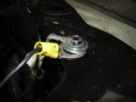
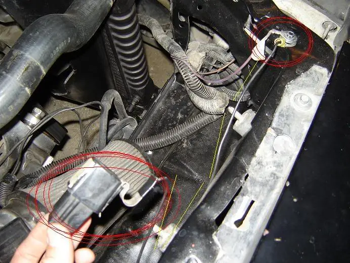
This is a picture of where it is grounded. Is this a sufficient ground? There is a washer in between. Should that conduct?
o23.webp


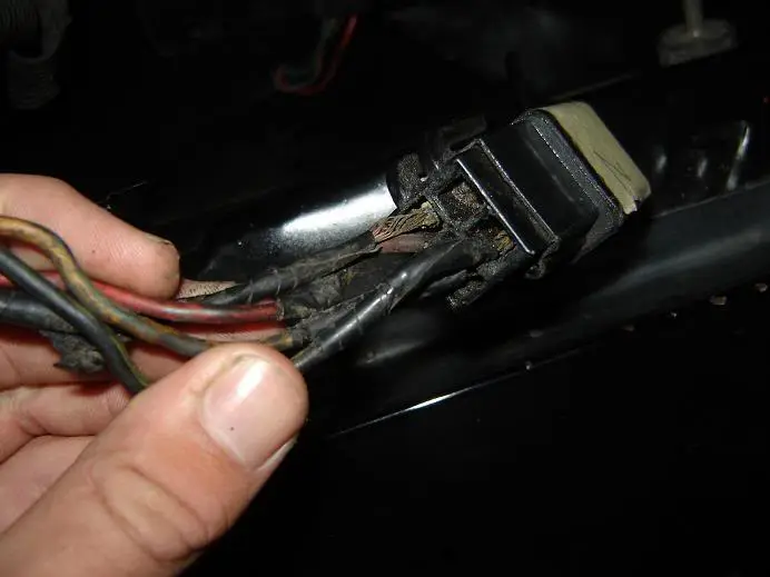
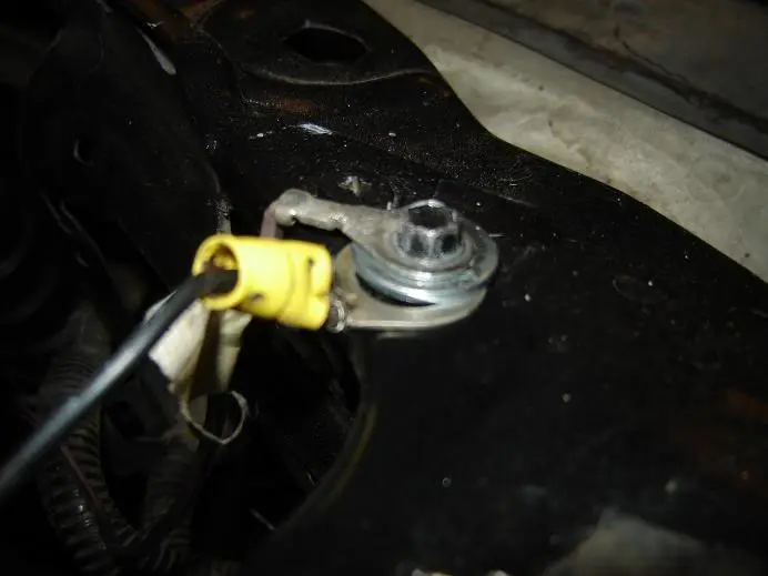
Here is a pic of the back of the box. Should something be connected to that empty hole? And yes i know I should be a hand model:D
o22.webp


This was also done on a cold engine
 

Attachments

  • o2.webp
    o2.webp
    63.4 KB · Views: 189
  • o23.webp
    o23.webp
    14.8 KB · Views: 137
  • o22.webp
    o22.webp
    16.7 KB · Views: 129
The pics must be huge - dial-up aint playing nice with me. I did see the oil level sensor in one pic - with what looks like a wire nut? :nice:

Rather than going backwards to find the issue, I'd put a DMM on each O2's signal wire. You'll see each one fluctuate quickly between ~ .1 and .9 volts. If so, I'd look elsewhere for the source of the lean condition (vac leaks, etc).

Jrichker has a post noting which wires at the computer are for the O2 signals. Last time I did it, I was under the car with my meter on each signal wire. :notnice:

Good luck.
 
Code 41 or 91 - O2 indicates system lean. Look for a vacuum leak or failing O2 sensor.

The computer sees a lean mixture signal coming from the O2 sensors and tries to compensate by adding more fuel. Many times the end result is an engine that runs pig rich and stinks of unburned fuel.

The following is a Quote from Charles O. Probst, Ford fuel Injection & Electronic Engine control:
"When the mixture is lean, the exhaust gas has oxygen, about the same amount as the ambient air. So the sensor will generate less than 400 Millivolts. Remember lean = less voltage.

When the mixture is rich, there's less oxygen in the exhaust than in the ambient air , so voltage is generated between the two sides of the tip. The voltage is greater than 600 millivolts. Remember rich = more voltage.

Here's a tip: the newer the sensor, the more the voltage changes, swinging from as low as 0.1 volt to as much as 0.9 volt. As an oxygen sensor ages, the voltage changes get smaller and slower - the voltage change lags behind the change in exhaust gas oxygen.

Because the oxygen sensor generates its own voltage, never apply voltage and never measure resistance of the sensor circuit. To measure voltage signals, use an analog voltmeter with a high input impedance, at least 10 megohms. Remember, a digital voltmeter will average a changing voltage." End Quote

Measuring the O2 sensor voltage at the computer will give you a good idea of how well they are working. You'll have to pull the passenger side kick panel off to gain access to the computer connector. Remove the plastic wiring cover to get to the back side of the wiring. Use a safety pin or paper clip to probe the connections from the rear. The computer pins are 29 (LH O2 with a dark green/pink wire) and 43 (RH O2 with a dark blue/pink wire). Use the ground next to the computer to ground the voltmeter.

Most of the common multimeters have a resistance scale. Be sure the O2 sensors are disconnected and measure the resistance from the O2 sensor body harness to the pins on the computer.

Note that all resistance tests must be done with power off. Measuring resistance with a circuit powered on will give false readings and possibly damage the meter. Do not attempt to measure the resistance of the O2 sensors, it may damage them.

The O2 sensor ground (orange wire with a ring terminal on it) is in the wiring harness for the fuel injection wiring. I grounded mine to one of the intake manifold bolts
 
Just fixed it!!!! All I did was clean the ground cables, warm up the engine, clear the codes, and all i got was 22 and 95!!! I had about 5 other codes before!!!!
 
I'm guessing that before today, you were not clearing the KAM after you tried something new..??
If so, you were seeing an old code when you tried something and rechecked them, or you have a regenerating code and it will be back yet again.

Good luck.
 
Code 22 MAP (vacuum) or BARO signal out of range. The MAP or BARO sensor is pretty much the same sensor for both Mass Air & Speed Density cars. The main difference is where it is connected. Mass Air cars vent it to the atmosphere, while Speed Density cars connect it to the intake manifold vacuum. Its purpose is to help set a baseline for the air/fuel mixture by sensing changes in barometric pressure. The MAP or BAP sensor puts out a 5 volt square wave that changes frequency with variations in atmospheric pressure. The base is 154 HZ at 29.92" of mercury - dry sunny day at sea level, about 68-72 degrees. You need an oscilloscope or frequency meter to measure it. There is no way you can use a common cheap voltmeter or DVM to accurately measure the output signal.

The MAP/BARO sensor is mounted on the firewall behind the upper manifold.

Baro or MAP test using frequency meter - run the test key on engine off. The noise from the ignition system will likely upset the frequency meter. I used a 10 x oscilloscope probe connected from the frequency meter to the MAP/BAP to reduce the jitter in the meter's readout.

If it is defective, your air/fuel ratio will be off and the car’s performance & emissions will suffer

Some basic checks you can make to be sure that the sensor is getting power & ground:
Note that all resistance tests must be done with power off. Measuring resistance with a circuit powered on will give false readings and possibly damage the meter.
Check the resistance between the black/white wire on the MAP/BARO sensor and then the black/white wire on the EGR and the same wire on the TPS. It should be less than 1 ohm. Next check the resistance between the black/white wire and the negative battery cablet. It should be less than 1.5 ohm.

The following power on check requires you to turn the ignition switch to the Run position.
Use a DVM to check for 5 volts on the orange/white wire. If it is missing, look for +5 volts at the orange/white wire on the TPS or EGR sensors. Use the black/white wire for the ground for the DVM.
 
The Speed Density cars had a MAP sensor.
The Mass Air cars had a Baro sensor.

All Sequential EFI engines had one or the other.

Both sensors are very similar in appearance. The difference in the two sensors in terms of appearance is that the Speed Density connect the sensor to the intake manifold while the Mass Air vent to the open air.

The following is a Baro sensor for a Mass Air car.
as13.jpg


The MAP Sensor for Speed density looks very similar.

2-19000.jpg
 
What did I just post in regard to what sensor works with what system?

Before you spend $75-$85 on a sensor, follow the instructions in the code 22 test path to check the wiring. It could save you some time and $$$.