Code 12 -Idle Air Bypass motor not controlling idle properly (generally idle too low) - IAB dirty or not working. Take it off and clean it thoroughly with throttle body cleaner. Clean the electrical contacts with non flammable brake parts cleaner at the same time.
Code 21 – ECT sensor out of range. Broken or damaged wiring, bad ECT sensor.
Note that that if the outside air temp is below 50 degrees F that the test for the
ECT can be in error.
The ECT sensor has absolutely nothing to do with the temperature gauge. They are
different animals. The ECT sensor is normally located it the RH front of the engine in
the water feed tubes for the heater.
The ACT & ECT have the same thermistor, so the table values are the same
ACT & ECT test data:
Use Pin 46 on the computer for ground for both ECT & ACT to get most accurate
readings.
Pin 7 on the computer - ECT signal in. at 176 degrees F it should be .80 volts
Pin 25 on the computer - ACT signal in. at 50 degrees F it should be 3.5 volts. It is
a good number if the ACT is mounted in the inlet airbox. If it is mounted in the lower
intake manifold, the voltage readings will be lower because of the heat transfer.
Voltages may be measured across the ECT/ACT by probing the connector from
the rear. A pair of safety pins may be helpful in doing this. Use care in doing it
so that you don't damage the wiring or connector.
Here's the table :
68 degrees F = 3.02 v
86 degrees F = 2.62 v
104 degrees F = 2.16 v
122 degrees F = 1.72 v
140 degrees F = 1.35 v
158 degrees F = 1.04 v
176 degrees F = .80 v
194 degrees F = .61
Note that all resistance tests must be done with power off. Measuring resistance
with a circuit powered on will give false readings and possibly damage the meter.
Ohms measures at the computer with the computer disconnected, or at the sensor
with the sensor disconnected.
50 degrees F = 58.75 K ohms
68 degrees F = 37.30 K ohms
86 degrees F = 27.27 K ohms
104 degrees F = 16.15 K ohms
122 degrees F = 10.97 K ohms
140 degrees F = 7.60 K ohms
158 degrees F = 5.37 K ohms
176 degrees F = 3.84 K ohms
194 degrees F = 2.80 K ohms
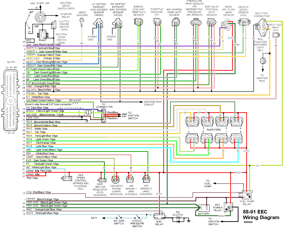
Diagram courtesy of Tmoss & Stang&2birds
See the following website for some help from Tmoss (diagram designer) & Stang&2Birds
(website host) for help on 88-95 wiring
http://www.veryuseful.com/mustang/tech/engine/
Ignition switch wiring
http://www.veryuseful.com/mustang/tech/engine/images/IgnitionSwitchWiring.gif
Fuel, alternator, A/C and ignition wiring
http://www.veryuseful.com/mustang/tech/engine/images/fuel-alt-links-ign-ac.gif
Complete computer, actuator & sensor wiring diagram for 88-91 Mass Air Mustangs
http://www.veryuseful.com/mustang/tech/engine/images/88-91_5.0_EEC_Wiring_Diagram.gif
Vacuum diagram 89-93 Mustangs
http://www.veryuseful.com/mustang/tech/engine/images/mustangFoxFordVacuumDiagram.jpg
There is no valid code 40 for a 5.0 Mustang. You probably got a 41.
Code 41 or 91 - O2 indicates system lean. Look for a vacuum leak or failing O2 sensor.
The computer sees a lean mixture signal coming from the O2 sensors and tries to compensate by adding more fuel. Many times
the end result is an engine that runs pig rich and stinks of unburned fuel.
The following is a Quote from Charles O. Probst, Ford fuel Injection & Electronic Engine control:
"When the mixture is lean,
the exhaust gas has oxygen, about the same amount as the ambient air. So the sensor will generate less than 400 Millivolts.
Remember lean = less voltage.
When the mixture is rich, there's less oxygen in the exhaust than in the ambient air , so voltage is generated between the two sides of the tip.
The voltage is greater than 600 millivolts. Remember rich = more voltage.
Here's a tip: the newer the sensor, the more the voltage changes, swinging from as low as 0.1 volt to as much as 0.9 volt.
As an oxygen sensor ages, the voltage changes get smaller and slower - the voltage change lags behind the change in exhaust gas oxygen.
Because the oxygen sensor generates its own voltage, never apply voltage and never measure resistance of the sensor circuit.
To measure voltage signals, use an analog voltmeter with a high input impedance, at least 10 megohms. Remember, a digital
voltmeter will average a changing voltage." End Quote
Testing the O2 sensors
Measuring the O2 sensor voltage at the computer will give you a good idea of how well they are working. You'll have to pull the
passenger side kick panel off to gain access to the computer connector. Remove the plastic wiring cover to get to the back side of
the wiring. Use a safety pin or paper clip to probe the connections from the rear. The computer pins are 29 (LH O2 with a dark green/pink wire)
and 43 (RH O2 with a dark blue/pink wire). Use the ground next to the computer to ground the voltmeter.
Note that all resistance tests must be done with power off. Measuring resistance with a circuit powered on will give false readings
and possibly damage the meter. Do not attempt to measure the resistance of the O2 sensors, it may damage them.
Testing the O2 sensor wiring harness
Most of the common multimeters have a resistance scale. Be sure the O2 sensors are disconnected and measure the resistance from the O2
sensor body harness to the pins on the computer.
The O2 sensor ground (orange wire with a ring terminal on it) is in the wiring harness for the fuel injection wiring. I grounded mine to
one of the intake manifold bolts
Replace the O2 sensors in pairs if replacement is indicated. If one is weak or bad, the other one probably isn't far behind.
Codes 44 & 94 - AIR system inoperative - Air Injection. Check vacuum lines for leaks, & cracks. Disconnect the big hose from
smog pump: with the engine running you should feel air output. Reconnect the smog pump hose & apply vacuum to the first vacuum
controlled valve: Its purpose is to either dump the pump's output to the atmosphere or pass it to the next valve. The next vacuum
controlled valve directs the air to either the cylinder heads when the engine is cold or to the catalytic converter when the engine is warm.
Disconnect the big hoses from the back side of the vacuum controlled valve and start the engine. Apply vacuum to the valve and see
if the airflow changes from one hose to the next.
The two electrical controlled vacuum valves mounted on the rear of the passenger side wheelwell turn the vacuum on & off under computer control.
Check to see that both valves have +12 volts on the red wire. Then ground the white/red wire and the first solenoid should open and pass vacuum.
Do the same thing to the light green/black wire on the second solenoid and it should open and pass vacuum.
Remember that the computer does not source power for any actuator or relay, but provides the ground necessary to complete the circuit.
That means one side of the circuit will always be hot, and the other side will go to ground or below 1 volt as the computer switches on that circuit.
The computer provides the ground to complete the circuit to power the solenoid valve that turns the vacuum on or off. The computer is
located under the passenger side kick panel. Remove the kick panel & the cover over the computer wiring connector pins. Check Pin 38 Solenoid
valve #1 that provides vacuum to the first Thermactor control valve for a switch from 12-14 volts to 1 volt or less. Do the same with pin 32
solenoid valve #2 that provides vacuum to the second Thermactor control valve. Starting the engine with the computer jumpered to
self test mode will cause all the actuators to toggle on and off. If after doing this and you see no switching of the voltage on and off, you
can start testing the wiring for shorts to ground and broken wiring. An Ohm check to ground with the computer connector disconnected &
the solenoid valves disconnected should show open circuit between the pin 32 and ground and again on pin 38 and ground. In like manner,
there should be less than 1 ohm between pin 32 and solenoid valve #2 and pin 38 & Solenoid valve #1.
If after checking the resistance of the wiring & you are sure that there are no wiring faults, start looking at the solenoid valves. If you
disconnect them, you can jumper power & ground to them to verify operation. Power & ground supplied should turn on the vacuum flow,
remove either one and the vacuum should stop flowing.
See the following website for some help from Tmoss (diagram designer) & Stang&2Birds (website host)
http://www.veryuseful.com/mustang/tech/engine/images/fuel-alt-links-ign-ac.gif
http://www.veryuseful.com/mustang/tech/engine/images/88-91eecPinout.gif
See
http://forums.stangnet.com/attachment.php?attachmentid=50477&d=1179965021 for a very nice drawing of the Thermactor Air System (smog pump) plumbing.
If you have a catalytic converter H pipe, you need to fix these codes. If you don't, then don't worry about them