replaced voltage regulator; still no juice

dochawk

New Member
Apr 12, 2023
28
1
3
At least now I'm sort of back on the road with it . . .

I was able to take it to get the alternator checked, by swapping in my van's battery. And to buy it a new battery (the 2019 battery was passing the simple test, but was still bad).

The voltage regulator failed, at least according to their machine--which surprised me by being done with the headlights on, and not the engine!

So I've pulled the alternator, replaced the voltage regulator, and it's still sending nothing to the battery.

I'm suspecting that the wiring harness is bad.

there's about 15-16v at the single terminal on the alternator.

The left connector should be the one carrying regulated voltage, shouldn't it?

alt_cnctr.jpg


I get something like 330k resistance from that pin to the "fusible link".

short of replacing the entire wiring harness under the hood, what options do I have?


get a new plug, and run a fat gauge wire to the link? (if so, what gauge?


use a sharp voltage indicator, and start poking my way around?
 
  • Sponsors (?)


On the 3 wire plug try applying 12v power to the 12v hot in run wire which should be green to see if the rectifier turns on with the engine running....If so you have wiring issues..

I suspect the problem is in the headlight harness given the other issues stated........

I'd Pull the harness and unwrap it....If you have a DVOM then you can trace circuits by doing a continuity test.

One time a freaky thing happened...I found out the hard way that my alternator was controlled through an idiot light that had a resistor built into the holder and when I changed the lightbulbs to LED it messed with the resistance and messed with the alternators function until I put the correct bulb back in...Even a dead bulb can cause issues as the lightbulb is needed to complete the circuit..

gauge panel).jpg

So if you turn the key to the ON position and you dont see this you may have an issue there...Plug B on the gauge panel pins 2 nd 14 are the ones of interest on most mustangs..

th (5).jpeg

Screenshot 2023-05-20 202059.jpg

They sell harness wrap on Amazon cheap and is way better to rewrap a harness with than using ooey gooey vinyl electrical tape..

IMG_20221023_144845.jpg

The ignition switch turns the alternator regulator on too..Depending on the year the wire is green and could also be red.

As you can see theres a spot in the tune where the ECU controls the alternator too.......


Good Luck Screenshot 2023-05-20 190158.jpg
 
Last edited:
This should be in the thread you already started. There is otherwise, no way for folks to know what you've already done.


my apologies. At that point, I took them as completely separate issues (although I'm coming to think that the bad voltage is behind multiple other problems, including the fuel pump protection circuit that led to the new tank, and . . .)


On the 3 wire plug try applying 12v power to the 12v hot in run wire which should be green to see if the rectifier turns on with the engine running....If so you have wiring issues..

I'm not sure which
I've got to do some digesting here, on how an alternator actually functions.

I found these images for the 99 crown Victoria on https://www.idmsvcs.com/2vmod/alternator/wiring/diagrams/index.html


1684874647382.png


1684874946263.png


So is pin 2 W/B the raw alternator output going to the voltage regulator, and available on pin 2 of the voltage regulator circuit?

And regulated current comes out pin 3 Y/W? And is it voltage "at all times" because it connects to the battery by way of the fuse box when off, but would send current back to the battery when the alternator is spinning?

And pin 1 LG/R goes to the battery indicator on the dash?

But if so, is that status from regulator to indicator, or a signal to the regulator to engage?
I suspect the problem is in the headlight harness given the other issues stated........

I'd Pull the harness and unwrap it....If you have a DVOM then you can trace circuits by doing a continuity test.

I have sharp probes coming for my meter on Friday.

So when car is off, I should see 12v on 3 Y/W, and open circuits for the other 2? And 3 LG/R would be ground, such that the indicator on the dash turns on when power is applied by the alternator not running yet?

And when car is on on, 3 Y/W would increase to operating voltage, a bit shy of 14, 2 W/B would be full alternator output of 15-16v.

And 3 LG/R would get operating voltage from the regulator side, which would be the same as the indicator light receives from the other side, causing no voltage drop across the lamp, which would therefore be off?

Or is the voltage passing through from the indicator light telling the alternator to engage the regulator? (so off voltage would still be around battery voltage, with most of the drop across the meter??)
One time a freaky thing happened...I found out the hard way that my alternator was controlled through an idiot light that had a resistor built into the holder and when I changed the lightbulbs to LED it messed with the resistance and messed with the alternators function until I put the correct bulb back in...Even a dead bulb can cause issues as the lightbulb is needed to complete the circuit..

I spent more than a day trying to figure out a heating problem on my '93 Fleetwood. Replacing the thermostat didn't help. And it turned out to be because . . . for reasons comprehensible only to Cadillac engineering, they used a standard thermostat housing coming out of the block, but the "thermostat assembly" or some such is on the bottom of the other side of the block. That housing should be empty, and my problems came about because someone had stuck a thermostat in, which later failed . . .


gauge panel).jpg

So if you turn the key to the ON position and you dont see this you may have an issue there...Plug B on the gauge panel pins 2 nd 14 are the ones of interest on most mustangs..

Is that plug in the engine compartment, or undertake dash? and can it be accessed without "heroic" measures like pulling the console (which I already need to do for the heater core).

They sell harness wrap on Amazon cheap and is way better to rewrap a harness with than using ooey gooey vinyl electrical tape..

I have some coming from Walmart today or tomorrow. I dumped amazon prime when I discovered that my neighborhood gets noticeably faster delivery from Walmart, and at the same or lower cost.

IMG_20221023_144845.jpg

The ignition switch turns the alternator regulator on too..Depending on the year the wire is green and could also be red.

so I should get close to battery voltage from the plug when disconnected?

As you can see theres a spot in the tune where the ECU controls the alternator too.......

great :)

Good Luck Screenshot 2023-05-20 190158.jpg


thanks. I'll poke as much as I can before my leads get here.

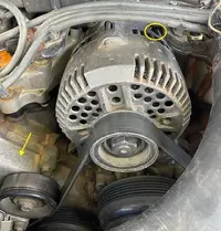
Oh, and the wiring on the plug doesn't look so good . . .

IMG_0747.jpeg


for that matter, should the wire from that middle pin be connected somewhere?

thanks

and one more question: is there a way to test the voltage regulator I removed out of circuit? everything I'm finding is just to check the system voltage.
 
Last edited:
Geeze those wires look awefully cracked up and very problematic....I would definately solder in and shrink sleeve in a new plug..They have them on ebay and Rock Auto if the local AP store near you doesnt carry one..

Can you take a picture of the type of alternator you have and post up the year of the car for a better referrence picture ?

I want to make sure you have the correct alternator for the plug wired in because both 2g and 3g alternators use all 3 wires but a 2g doesnt have the lil stator plug end.......

I hope the rest of the harness isnt the same but as far as the plug and such the middle one with the lil plug is called the stator wire and the green with red stripe will be the one carrying the 12v of power when the keyswitch is turned to the ON position and the power should be the same as the battery voltage so measure the battery voltage with the keyswitch turned to the ON position too....

Make sure to test the battery with the keyswitch ON because you'll get two different voltage readings .............

The lil stator plug goes here on a 3g alternator... when the regulator is energized the white wire adds voltage to the stator to create a charge by activating an electromagnet.

Another thing to note is if you do have a 3g alternator having a really good alternator body to engine block ground is paramount aswell as having a seperate ground wire of atleast 4 gauge attached to the back too.......

Screenshot 2023-05-23 225548.jpg
unnamed (2).jpg
 

Attachments

  • 99a89284.gif
    99a89284.gif
    77 KB · Views: 46
Last edited:
Geeze those wires look awefully cracked up and very problematic....I would definately solder in and shrink sleeve in a new plug..They have them on ebay and Rock Auto if the local AP store near you doesnt carry one..

I have a decent supply of inline crimp connectors. And apparently my new plug came about a half an hour after midnight. unfortunately, all three leads are black.
Can you take a picture of the type of alternator you have and post up the year of the car for a better referrence picture ?

IMG_0750.jpeg


I hope the rest of the harness isnt the same

not admirable, but this is among the worst.

The lil stator plug goes here on a 3g alternator... when the regulator is energized the white wire adds voltage to the stator to create a charge by activating an electromagnet.

hmm. that's not connecting without pulling the alternator again, is it? At least it's a lot easier than the serpentine on my E150 . . .


Another thing to note is if you do have a 3g alternator having a really good alternator body to engine block ground is paramount aswell as having a seperate ground wire of atleast 4 gauge attached to the back too.......

OK, this may be really bad.

there's an open circuit between the alternator body and ground! Even on the 20M range, it shows *no* continuity!

I also tested the bolt holding the alternator down' it's somehow not grounded either!
The piece that the yellow arrow above points to is nicely grounded.

I guess 4ga on a loop connector from one of the bolts holding it down to a good ground? And where should I find that good ground?


The R/G wire has a couple tenths a volt less than the battery voltage, both when simply on and with the engine running.
 
Alrighty then ...You do have an original 3g alternator and I took your picture and circled the area the stator plug plugs into....

As far as the plug wires being all black thats no issue at all ...Just put the white wire w plug in the middle and then use the old plug as a guide to attch the other 2 wires....The connector is D shaped so its easy to reference it easily..

Just dont be too surprised if the alternator still doesnt work or works inefficiently because when the stator wires get as tarnished as yours means that the stator got hot enough to burn the protective clearcoat off the copper and that usually causes dead shorts....The 3rd pic shows how your copper wiring in your stator should appear like and 4th pic shows what a burnt stator looks like..

BTW it looks like you have some pretty wicked coolant leaks too....Have you tried tightening the intake manifold bolts a lil?

Another thing I noticed is the water stains are pretty rusty which usually means the radiator is coming close to needing to be replaced..

Sometimes the radiator flush in the bottle doesnt cut the mustard as you can see from the second picture.......LOL


Have a good weekend.
 

Attachments

  • download.jpg
    download.jpg
    482 KB · Views: 48
  • IMG_20211006_163130.jpg
    IMG_20211006_163130.jpg
    561.5 KB · Views: 41
  • 111-Ford-alternator-reclocking-hits-long-mounting-ear.jpg
    111-Ford-alternator-reclocking-hits-long-mounting-ear.jpg
    667 KB · Views: 38
  • Screenshot 2023-05-27 024046.jpg
    Screenshot 2023-05-27 024046.jpg
    71.2 KB · Views: 38
Last edited:
Alrighty then ...You do have an original 3g alternator and I took your picture and circled the area the stator plug plugs into....

a-hah!

that notch hides under the spark wire guide plate.


As far as the plug wires being all black thats no issue at all ...Just put the white wire w plug in the middle and then use the old plug as a guide to attch the other 2 wires....The connector is D shaped so its easy to reference it easily..


I seem to be somewhere between:


Just dont be too surprised if the alternator still doesnt work or works inefficiently because when the stator wires get as tarnished as yours means that the stator got hot enough to burn the protective clearcoat off the copper and that usually causes dead shorts....The 3rd pic shows how your copper wiring in your stator should appear like and 4th pic shows what a burnt stator looks like..

alternator_coils.jpg


it was generating close to 16v when I tested at the single terminal, but I have no idea if it can put out the current.

BTW it looks like you have some pretty wicked coolant leaks too....Have you tried tightening the intake manifold bolts a lil?

This whole thing started with the manifold going bad!

It was using more water than gas, and I replaced it.

I didn't have the throttle attached yet (a bit of one of the pieces broke). It would start, and then race, so i
d have to kill it quickly.

And then it suddenly stopped starting, and I figured that I'd lost signal to the injectors.

And then covid happened, and it sat fora couple of years.

I brought a mobile mechanic to help, and we traced lack of fuel pressure back to the pump. We pulled the tank, and it looked like NASA shots of the martian surface. So tank & fuel pump got replaced.

In hindsight, it was probably the fuel pump safety circuit simply needing to be reset . . . as it was last week when I thought I'd run the battery down too far, then we added gas as the gauge red low, and . . . pushing reset did it.

and it still has a significant leak.

so, anyway, I pulled the alternator and put the old voltage regulator back on, connected the stator line as well as the D-plug, and started up.

I ended up stopping early, as I was dropping to many parts, and having trouble figuring out which bolt wen there.

I'll take itup again Monday morning.

thanks again
 
As my curiosity grew, I pulled the alternator, put the original voltage regulator back on, and brought it in for testing.

Out of the car, the voltage regulator passed, and it went on to fail the alternator itself.

So I ordered a cheap one that didn't need a core, figuring to either rebuild this one at my leisure (yeah, i have odd tastes and am easily amused, I suppose), or use it as the core to get the new one my van needs (although not this urgently), rebuild *that* one, and put it in the mustang (same part,it's an '02 E150).

It arrived quickly (7:30 A.M. two mornings later), I took stout to the care, and . . . it's the wrong alternator. It might be for a Honda, looking at the pictures, but it uses vertical, rather than horizontal, bolts.

:rolleyes:

It even has the part number for the one I need on the factory decal! (I suppose the other possibility is that autozone has the wrong data, but that means that every single one they ever sold would have come back!).

So now I wait for the new one, and contemplate using the van to push the mustang two feet forward off the sidewalk . . .
 
So I ordered a cheap one that didn't need a core, figuring to either rebuild this one at my leisure (yeah, i have odd tastes and am easily amused, I suppose), or use it as the core to get the new one my van needs (although not this urgently), rebuild *that* one, and put it in the mustang (same part,it's an '02 E150).
I will say that any rebuild by either you or a local shop is going to be 10 times better than any Chinese reman you get from a parts store. It's def worth doing if you're into that sort of thing.
 
hmm, with some quick searching, it looks pretty straightforward, assuming I can find the kit.

Disassemble, clean, replace brushes, and possibly bearings, rectifier and voltage regulator?

But I'm not seeing anyone offer delivery in less than a week and a half.

ok, found one that delivers in less than a week, but doesn't include a rectifier, stating that they rarely fail.
 
Last edited:
Also, look around for [motor rebuild shops]. The last guy I dealt with worked right out of his garage, had parts, and gave me back the starter (in this case) a day later. It looked like he did a bit of everything. We had an old standing shop fan motor he rebuilt for us too.
 
I have it mostly apart.

Looks like the copper can use some serious cleaning. Carb cleaner?

IMG_0772.jpeg


IMG_0774.jpeg


There is a crack on this plastic (*?) on one of the bearings:

IMG_0771.jpeg


I take it that this big arc in the yellow box is the rectifier? Can I test it with a meter? (and how?)

IMG_0767.box.jpg
 
Funny thing happened when my 3g went out, I replace the regulator and it still wasn't charging.
I checked the mega fuse and wouldn't ya know it was blown.
 
my rebuild kit arrived this morning.

What I *can't* find in any the instructions I've found is how to remove the bearings, or the pulley.

I've seen a couple refer to using a puller on the bearings. Would this mean garden variety gear pullers? I have a set from my adventures with the swamp cooler--it only cost $5 more than the single puller I headed, or some such.

I'm not sure I really need to remover the pulley, but how to get it off is vexing me. It's a 15/16 nut (not a size I expected to find on a vehicle this recent. There only one I have is from my *grandfather's* tool chest . . .). But that would require holding the pulley still. A few places say to use an air gun, but that still leaves the question as to how to hold the pulley still while spinning the nut.
 
Use an old belt and with impact gun it'll come off easy. Then thread but back by hand a few threads and tap with hammer lightly to remove pulley.
When you take case apart the bearing is held in with a plate that screws in to housing. It's easy.i
Make sure you check mega fuse,
 
and I even have an old torn western belt that I couldn't bring myself to throw out.

I guess hat would also give me a way to grasp the pulley with a wrench or vise without damaging those soft metal threads.

I took it by an o'riely's after I put in the regulator and armature.

Their machine got toasted last night by a renegade alternator they texted.

So across the intersection to Autozone, where it wouldn't give them an explanation of what it didn't like about how they connected it.

To Napa two doors down, which doesn't have. tester.

To another autozone a couple of miles away, at which point I noticed the bully didn't spin freely, as I had't tightened the bolts enough.

tomorrow is another day . .
 
well, rats.

I got the large bearing off with a belt and air hammer (it was so easy that I suppose my 18v impact driver could have done it, had I had the adaptor on hand).

reassembled, so no it has everything replaceable replaced except for the small bearing (but I have an extractor arriving in a couple of days).

I took it into a different oreilly's, and it fails it without even starting the test.

the shaft spins freely.

So what is left to try?

(put the old regulator back on with the new armature, perhaps?)

is there a way to test the regulator out of circuit?
 
the small puller supposedly arrives today, so I'll replace it tomorrow .

My rebuild kit didn't have a slip ring; do I simply test the old one, looking for 3 or 4 ohms?

And it would sure be nice if there was a picture of th rectifier *with* the schematic superimposed. this would make it *so* much easier to test. If I figure it out, I'll post one all over the place.