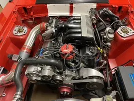
I recently picked up an 89 GT with a 347 stroker. After spending some time at a tuner to get it road ready I got to bring it home and noticed some oil leaking on to the header causing a potential hazard and small amounts of smoke.
Most everything has been removed from the engine bay AC / EGR as it is shaved with very easy access to just about every component of the motor.
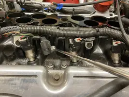
The issue : Oil leaking from left side of the head (facing the motor. or the passenger side.
Can I get some indepth guidance on what steps I should follow to remove the intake/ headers / manifold and then the heads? Is this a simply step by step porcess of unbolting parts placing then aside?
If these is a simple bolt off task after I get the heads off do I
Clean the surface thoroughly with a razor blade
Apply gasket goo. Peramtex? What is recommended? Apply this liberally or sparingly? What areas exactly?
Place the head back on the fresh clean surface with Permatex
Bolt to spec and then re bolt everything back together the way it came off?
Do I need any additional parts to accomplish this?
The goal is take off put back and fire it up running as it should prior to taking it apart? Is this possible
Thanks for the input!
Cylinder head removal & replacement
Revised 25-Aug-2014 to update parts list
Plan on 3 days to do the job if you haven't done it before.
Day one gets the heads off in 4-6 hours. Remove the A/C compressor mount bolts and move the compressor out of the way. The A/C compressor swings out of the way without disconnecting any of the lines or losing any refrigerant. Mark all the electrical, smog and vacuum lines with tags to help you remember where to re-connect them. If you have a digital camera, take several pictures.
Day two gets all the gasket surfaces scraped off extra clean and the heads dropped off at the machine shop if you are going to have them reconditioned. Time here is another 4-6 hours. Whatever you do, don't skimp on cleaning the gasket surfaces. New gaskets need to seat against bare metal and not the residue left from the old gaskets in order to seal leak free. This is the most time consuming and tiresome part of the job. Look for little things that need to be replaced like the short hose from the thermostat hosing to the water pump, damaged vacuum lines and hose clamps that are rusted or broken.
Day three starts when you get the heads back from the machine shop. This is the time to pick up all the little odd pieces you found needing replacement on your day two inspection/cleanup. Plan on 6-8 hours to reinstall the heads and reconnect everything. Plan on an additional 2 hours to troubleshoot/adjust everything.
Now for some practical tips:
Tools: a good torque wrench is a must have item. A razor blade scraper that holds a single edge razor blade from Home Depot or Ace hardware is another handy thing. Get a Chilton or Haynes shop manual - you'll need it for the bolt torques and patterns. The intake manifold has an especially odd pattern.
Diagram courtesy of Tmoss & Stang&2birds
The bolts are torqued down in a 3 step process.
Step 1 8 ft/lbs
Step 2 16 ft/lbs
Step 3 23-25 ft/lbs
You'll need access to a timing light to set the timing after you re-stab the distributor. Look in the A/C repair section for the fuel line tools. They look like little plastic top hats. You will need the 1/2" & 5/8" ones. The hat shaped section goes on facing the large part of the coupling. Then you press hard on the brim until it forces the sleeve into the coupling and releases the spring. You may need someone to pull on the line while you press on the coupling. Put some motor oil on them when you put the line back together.
Whatever you do, don't skimp on cleaning the gasket surfaces. New gaskets need to seat against bare metal and not the residue left from the old gaskets in order to seal leak free. This is the most time consuming and tiresome part of the job. Look for little things that need to be replaced like the short hose from the thermostat hosing to the water pump, damaged vacuum lines and hose clamps that are rusted or broken.
Put some cardboard in the lifter valley to help catch the gasket scrapings. Have a shop vacuum handy to suck up the scrapings and any coolant that leaked into the lifter valley.
Plan on cutting the thermostat to water pump hose, or removing the thermostat housing. Also plan on removing the distributor to get clearance to remove the intake manifold. Remove #1 spark plug, stick your finger in the spark plug hole and crank. When your finger gets air moving past it, stop cranking. Turn the engine until the timing marks line up with the pointer. Now you can pull the distributor out. Be sure to put a rag or cap in the block where you removed the distributor. It will save you trouble if something falls into the empty distributor hole.
My favorite trick that saves time and effort is the stay in place gasket. Be sure that you scrape (don't use a wire brush) all the old gasket material off, then clean all the surfaces with acetone or MEK.
When the surfaces are clean, use weather strip adhesive on the head to manifold surface, and on the side of the gasket that mates to the head. Follow the instructions on the tube or can and when it gets tacky, press the gasket down on the head.
Clean the area where the rubber rails mount to the block in front and in the rear with more acetone or MEK and do the same trick with the weather strip adhesive that you did to the heads.
Coat the rubber seals and the gasket area around the water passages with Blue Silicone gasket sealer and put it together. Whoopee! no leaks, and no gaskets that shifted out of place.
Get a tube of anti-seize and coat all the bolt threads and under the bolt heads. That will help insure even torque when you tighten the manifold bolts. Plan on re-torqueing them after a week’s worth of driving
The cylinder head bolts are reusable, but some new ARP bolts are a better plan.
Caution!!! Be aware that the ARP bolts have a radiused shank under the bolt head. The ARP washers have a matching radius machined into them. Be sure that the machined radius of the washer is fitted next to the machined radius on the ARP bolt heads. Forget this little fact and you will never get the head bolts to torque down properly.
Coat the underside of all bolt heads with anti seize and the threads of the long bolts. The short bolts thread directly into the water jacket and need a different treatment. Use Teflon Pipe dope on the threads of the short head bolts. It will prevent any coolant seepage from around the threads. You can get the Teflon pipe dope from the hardware stores, Home Depot or Lowes.
Fuel injector seal kits with 2 O rings and a pintle cap (Borg-Warner P/N 274081) are available at Pep Boys auto parts. Cost is about $3-$4 per kit. The pintle caps fit either injectors with a pin sticking out the injector end or 4 with more tiny holes in the injector end. The following are listed at the Borg-Warner site (
BWD - Home ) as being resellers of Borg-Warner parts:
Parts Plus - Premium Auto Parts & Accessories or
Auto Value / Bumper to Bumper Quality Parts & Service - Home of the Aftermarket Auto Parts Alliance Group or
Tires, Auto Parts Stores, Brakes & Automotive Parts | Pep Boys or
Federated Auto Parts - Automotive Aftermarket
Most of the links above have store locators for find a store in your area.
Use motor oil on the O rings when you re-assemble them & everything will slide into place. The gasoline will wash away any excess oil that gets in the wrong places and it will burn up in the combustion chamber.
Putting the distributor back in is fairly simple. Pull #1 sparkplug, put your finger in the sparkplug hole,
crank the engine until you feel compression. Then line up the TDC mark on the balancer with the pointer
on the engine block.
The distributor starts out with the #1 plug wire lined up at about 12:00 with you facing it. Align the rotor
to about 11:00, since it will turn clockwise as it slides into place.
Align the distributor rotor up with the #1 position marked on the cap, slide the distributor down into the block, (you may have to wiggle the rotor slightly to get the gear to engage) and then note where the rotor is pointing. If it still lines up with #1 position on the cap, install the clamp and bolt. If not, pull it out and turn 1 tooth forwards or backwards and try again. Put the #1 spark plug back in and tighten it down, put the clamp on the distributor, but don't tighten it too much, as you will have to move the distributor to set the timing. Note that if it doesn't align perfectly with #1 position, you can turn the distributor until it does. The only problem is that if you are too far one way or the other, you can't turn the distributor enough to get the 10-14 degree optimum timing range.
At this point hook up all the wires, get out the timing light and start the engine. Set the timing where your car
runs best. Don't forget to disconnect the SPOUT jumper connector when you set the timing, and plug it back
in when you finish.
The HO firing order is 1-3-7-2-6-5-4-8.
Non HO firing order is 1-5-4-2-6-3-7-8
Consumable items:
head gaskets or head gasket kit
Rocker cover gaskets
Upper manifold gasket
Fel Pro 1250 or equal lower manifold gasket set.
Exhaust manifold gaskets.
Short formed hose between thermostat hosing and intake manifold
6 ft 7/64" or 1/8" vacuum hose
2 ft 1/2" heater hose
1 1/2 ft 5/8" heater hose
Blue Silicone sealer
Spray can weather strip adhesive to hold manifold gaskets in place
Acetone or MEK to clean gasket surfaces
1 gallon straight antifreeze (same price as 50/50 mix, but a 90 cent gallon of distilled water makes it 2 gallons at a cheaper price)
1 gallon distilled water
ARP antiseize or equal for the bolts
Teflon Pipe dope
4 each 3/4" hose clamps (spare item in case the old ones are bad)
4 each 1/2" hose clamps (spare item)
Machine shop charges will vary - figure $275-$350 to have heads checked for cracks, cleaned, surfaced, valves ground, valve guides reconditioned, valve springs checked and bad springs replaced.
See the following website for some help from Tmoss (diagram designer) & Stang&2Birds (website host) for help on 88-95 wiring
Mustang FAQ - Wiring & Engine Info Everyone should bookmark this site.
Ignition switch wiring
http://www.veryuseful.com/mustang/tech/engine/images/IgnitionSwitchWiring.gif
Fuel, alternator, A/C and ignition wiring
http://www.veryuseful.com/mustang/tech/engine/images/fuel-alt-links-ign-ac.gif
Complete computer, actuator & sensor wiring diagram for 88-91 Mass Air Mustangs
http://www.veryuseful.com/mustang/tech/engine/images/88-91_5.0_EEC_Wiring_Diagram.gif
Vacuum diagram 89-93 Mustangs
http://www.veryuseful.com/mustang/tech/engine/images/mustangFoxFordVacuumDiagram.jpg
HVAC vacuum diagram
http://www.veryuseful.com/mustang/tech/engine/images/Mustang_AC_heat_vacuum_controls.gif
TFI module differences & pin out
http://www.veryuseful.com/mustang/tech/engine/images/TFI_5.0_comparison.gif
Fuse box layout
http://www.veryuseful.com/mustang/tech/engine/images/MustangFuseBox.gif