
Im planning out my next project, a torque arm. im going to build it myself and i have been studying up on the different kinds of mounting points they use .
first : front mounts
so the first style is the "stick and hole" mount. this is used by maximum motorsports and is basically a bolt sticking out the end, wrapped in 2 polyurethane bushings, and stuck into a pipe/tube thats got a zerk fitting on it. This is the first torque arm i looked at online and i figured there should be a better way to do this. not only will a single bolt shear catapult you to doom, it just seemed way too primitive to have a side load on a bushing that is supposed to longitudinally plunge with heavy side loads, with substandard "greasability" .


here is another derivation of this style i found on spohn's site:

along with this derivation, the older spohn style two- piece:
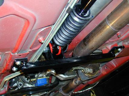

The second kind ive come across is the "sandwich" method. this is basically plate steel with a hole though it---- urethane bushing--- another steel plate ---- and another urethane bushing--with the bolt going through them all. This is griggs style front mount. This is a cheesy design. Ill refer to this style furthermore as the cheeseburger. The cheeseburger is old school industrial revolution **** right there. youd have to have it loose so it could move, but that would let it slap around and make noises, maybe scare your female passenger while youre trying to lay some mack down. "i think your car is broken" i dont want to hear that. so this design is a no go.


The third kind ive recently seen is the "chain link" style. Not a chain link like a dungeons and dragons chain, more like a huge motorcycle or bike chain. its kinda like one of those attached at one end to the crossmember and one end on a heim which comes from the arm itself. This is the most complicated, so its obviously the best :hmm:. This type is used on the updated crap maro spohn torque arms. it can swivel on the rear articulation using the heim joint to be the pivot. it can also have some forward and aftward movement because of the chain link piece. this seems like a tight setup and would not slap and make noise like the previous two could from accel- unclutched decel or the opposite. While this would prevent slap noise though, the other two had urethane mounting points, this one is straight metal to metal to metal... so it would transmit alot more harmonics from the rear and be a little harder on everthing componentwise. Also, it still has a single bolt to shear like the MM bar, catapult machine.


and minus the chain link:

http://www.ws6transam.org/car/torqarm5.jpg[/img
^^i like the added feature of the saftey "cage" he has for a backup measure if the heim is to fail.^^
ok so where are we at. pros vs cons, what would you guys do? any feedback or input?
i was thinking i would do just the heim with no chain line\k, will this cause bind with urethane rear control arms? solid rear arms?
next up, rear mount:
There are only two syles i have looked at. First up, the maximum motorsports style. this is a bolt on 4 u bolts over the axle tubes and two bolts throught the diff housing webs. this looks like a pretty allright design to me. When the rear wants to twist, the two web bolts are the oly solid links to fighting the cars torque and keeping the rear straight though.
[img]http://www.alanchavis.com/oldsite/mmtapb/dcp_1690.jpg


^^look at those skinny u-bolts^^


the second style is found on the griggs torque arm and on the steeda 5-link (kinda). it uses the bolts on the rear end cover to hold it on the back, then the same two bolts in the webbing the MM piece had. this seems ok if you redrill, tap, and install bigger grade 8 bolts and use some pretty thick flat steel for the mount. this would have a better position to controll torque and would seem stronger if done correctly, but i hear you must use an aftermarket diff cover. This doesnt sound that bad, just change a cover, but opening a rear end smells like the most putrid **** i have ever smelled. that smell sticks in my nose for like 2 days, and its gonna stink up my oil catch pan for a while and id rather not go in there if it can be avoided.
the pics seem like the brackets may have nipples that have to be put in the rear bolt holes.? i assume the rear bolt holes this bolts to have to be counterdrilled so the inserts can go in..?? idk...


so whats youre opinion on the rear mount?
i want to do a wrie up on this so other people can avoid the price tag and maybe create a hybrid imporved version on both.
-jay
first : front mounts
so the first style is the "stick and hole" mount. this is used by maximum motorsports and is basically a bolt sticking out the end, wrapped in 2 polyurethane bushings, and stuck into a pipe/tube thats got a zerk fitting on it. This is the first torque arm i looked at online and i figured there should be a better way to do this. not only will a single bolt shear catapult you to doom, it just seemed way too primitive to have a side load on a bushing that is supposed to longitudinally plunge with heavy side loads, with substandard "greasability" .
here is another derivation of this style i found on spohn's site:
along with this derivation, the older spohn style two- piece:
The second kind ive come across is the "sandwich" method. this is basically plate steel with a hole though it---- urethane bushing--- another steel plate ---- and another urethane bushing--with the bolt going through them all. This is griggs style front mount. This is a cheesy design. Ill refer to this style furthermore as the cheeseburger. The cheeseburger is old school industrial revolution **** right there. youd have to have it loose so it could move, but that would let it slap around and make noises, maybe scare your female passenger while youre trying to lay some mack down. "i think your car is broken" i dont want to hear that. so this design is a no go.
The third kind ive recently seen is the "chain link" style. Not a chain link like a dungeons and dragons chain, more like a huge motorcycle or bike chain. its kinda like one of those attached at one end to the crossmember and one end on a heim which comes from the arm itself. This is the most complicated, so its obviously the best :hmm:. This type is used on the updated crap maro spohn torque arms. it can swivel on the rear articulation using the heim joint to be the pivot. it can also have some forward and aftward movement because of the chain link piece. this seems like a tight setup and would not slap and make noise like the previous two could from accel- unclutched decel or the opposite. While this would prevent slap noise though, the other two had urethane mounting points, this one is straight metal to metal to metal... so it would transmit alot more harmonics from the rear and be a little harder on everthing componentwise. Also, it still has a single bolt to shear like the MM bar, catapult machine.
and minus the chain link:
http://www.ws6transam.org/car/torqarm5.jpg[/img
^^i like the added feature of the saftey "cage" he has for a backup measure if the heim is to fail.^^
ok so where are we at. pros vs cons, what would you guys do? any feedback or input?
i was thinking i would do just the heim with no chain line\k, will this cause bind with urethane rear control arms? solid rear arms?
next up, rear mount:
There are only two syles i have looked at. First up, the maximum motorsports style. this is a bolt on 4 u bolts over the axle tubes and two bolts throught the diff housing webs. this looks like a pretty allright design to me. When the rear wants to twist, the two web bolts are the oly solid links to fighting the cars torque and keeping the rear straight though.
[img]http://www.alanchavis.com/oldsite/mmtapb/dcp_1690.jpg
^^look at those skinny u-bolts^^
the second style is found on the griggs torque arm and on the steeda 5-link (kinda). it uses the bolts on the rear end cover to hold it on the back, then the same two bolts in the webbing the MM piece had. this seems ok if you redrill, tap, and install bigger grade 8 bolts and use some pretty thick flat steel for the mount. this would have a better position to controll torque and would seem stronger if done correctly, but i hear you must use an aftermarket diff cover. This doesnt sound that bad, just change a cover, but opening a rear end smells like the most putrid **** i have ever smelled. that smell sticks in my nose for like 2 days, and its gonna stink up my oil catch pan for a while and id rather not go in there if it can be avoided.
the pics seem like the brackets may have nipples that have to be put in the rear bolt holes.? i assume the rear bolt holes this bolts to have to be counterdrilled so the inserts can go in..?? idk...
so whats youre opinion on the rear mount?
i want to do a wrie up on this so other people can avoid the price tag and maybe create a hybrid imporved version on both.
-jay

 .
.


