Torsional rigidity test: 67 coupe

I'm curious what you would get if you used all the convertible reinforcements on a hardtop (extra rockers, boxing under seats, torque boxes, one piece seat riser, etc.). SN65 is doing something like that at the moment, but I don't think he has posted the end results yet.

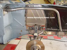
One nice thing about using factory sheetmetal for the reinforcements (Export Brace, torque boxes etc.) is that they they look like they belong there. If you like that look is of course a matter of taste.

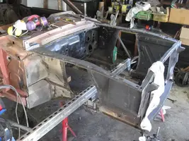
I think the conv. sheetmetal would help. Not only do they look right but they are prefabricated to fit! The boxing under the seats would be easy to tie into the subframe connectors and would tie them to the rockers. I thought about using the 1 piece seat risers but I would need to lower them so I can put modern seats in there and still be able to fit in the car.
 
New info. A suggestion to move the jackstands to try to isolate where the flex revealed a flaw in my method.

But first, to make sure the nylon straps I used to hold down the car were not stretching I replaced one with this turnbuckle.

turnbuckle.webp


Before and after measurements confirmed that the straps were not stretching.

New baseline to account for overnight settling, heat, gravity.... 0.62"

New rear mounting point. I moved the right rear jackstand forward to the front leaf spring mount. Retest: 0.52". Significant difference but most of the flex is still between the front spring mount and the radiator support.

Next step. Move the torque bar to the upper control arm mounts. Rear jackstand still at the front spring mount. Deflection: 0.35" Wow.

newtorquearmlocation.webp


Next step was to move the rear jackstand back to the original point. 0.45"

This means that about 27% of the flex I was measuring was forward of the control arm mount.

I'm undecided on how to proceed. Use the original loading location for future mods or make all further measurements with respect to the suspension mounts. Using the forward location made it easy to compare the stock and MII configurations but the real need is to limit twist between the front and rear suspension attachment points. Of course changing now makes comparisons to the data collected so far meaningless.
 

Attachments

  • newtorquearmlocation.webp
    newtorquearmlocation.webp
    56.6 KB · Views: 870
I asked my wife the structural engeneer to come look at this thread. Talk about opening a can of worms. She does seismic retrofits, and I can hardly understand a word she says after I ask her a question like this, but I'll try.

Basically, you're screwed, but you've already articulated why.

You can measure defection at the core support, but the measurement is meaninless because you don't apply any torque there anyway.

You can't measure deflection under the shock towers becasue you have to cut them off to get the bar in.

I've seen the Mustang II conversions fail right behind the crossmember. It breaks the frame. My wife explained that taking the shock towers and export brace out moves the load path and the beam deflection from being shared with the cowl and concentrates them on the frame rails. The problem then becomes that the whole car rides on the framerails, and they weren't designed to take that sort of load. Which explains the failures I've seen.

If I were you, the big deflection you got when you pulled the export brace but would be my major concern. I don't know/have any ideas how you get the loadpaths back from the crossmember to the cowl now that you've removed the shocktowers, but that would be where I would focus my energy.

Hope this helps.

Good point craigmba. The flex is for the most part meaningless outside of the suspension mount locations. However, one way to get a more accurate result would be to have your rear jacking at the front spring perch, and the front jacking/torquing to be at the front suspension points. How about removing the lower control arms and mounting the beam in their place?
 
Jacking rails or stringers

They connect the subframe connetors to the rocker panels to further reduce twist. I found these by searching for "Mustang subframe connectors." I also found examples of the Kenny Bell brand but they look less substantial.

I think these are an excellent idea. I have a convertible (obviously) and the convertible reinforcement that links the two rockers together midfloor. That, combined with the center plate that bolts in, does a lot from all that I have read about coupe and fastback owners installing it.

I added to it Tinman subframe connectors that insert and weld in the front frame rails and weld to the rear. These in turn bisect the convertible floor reinforcement and are welded to it. So I basically have a "T" or a cross midspan. Now, when I jack up the left rear corner for example the front left comes right up with it. I firmly believe that tying the subframes to a midspan convertible reinforcement is the way to go. Stronger convertible rocker panels also help, as there is a lot of strength there. That being said, I'd still add the stringers connecting my Tinman subframes to that rocker panel, probably with the 1x1 welded to the subframes to provide a suitable surface to weld do. It's a convertible, so it can't hurt.

P1000120.jpg


I won't be able to give a real proper review until I have a rear suspension to match my front, but the basic seat-of-pants feel is that I have a lot of strength midspan but some flex ahead of the firewall and at the rear. But until my rear leafs get replaced, that's pretty unscientific.
 
Good point craigmba. The flex is for the most part meaningless outside of the suspension mount locations. However, one way to get a more accurate result would be to have your rear jacking at the front spring perch, and the front jacking/torquing to be at the front suspension points. How about removing the lower control arms and mounting the beam in their place?

mrmustangman357,

It was on your suggestion that I started moving things around. I orignally thought about cutting holes in the shock towers to put the torque bar through so I could compare the chasis at the suspension mounts but in the end took the easy way out. I didn't think about mounting the bar to the lower control arm mounts and that might have worked but it's too late as the original metal is now a pile of junk.

I like what the SN65 guys did but, of course, I don't have their equipment. I think from here on out I will attach the bar at the uca mounts and place the rear jackstands at the front leaf mount. This will allow me to isolate the area between the suspension but I may still do some tests at the front to see how the changes compare to stock.
 
I think from here on out I will attach the bar at the uca mounts and place the rear jackstands at the front leaf mount. This will allow me to isolate the area between the suspension but I may still do some tests at the front to see how the changes compare to stock.

Great thread, thread of the year in my opinion. :nice:

I think this is the best you can do. And going back and doing a few tests from the front will still give a means to compare to stock a little bit.

Off topic - maybe we should have awards for Best Tech Thread Of the Year and Best Talk Thread of the Year. (maybe start a different thread to discuss it)
 
Great thread, thread of the year in my opinion. :nice:


I agree with this.

It's been a long time since I sat completely upright in my chair and read and reread a post to make sure I wasn't missing something.:D

I've done the basics like most of the rest of you guys but, I've been thinking about switching to the boss crossmember and plating behind the rear seat to help.

I'll be following this closely.


By the way, who has a S.E. for a wife? Lucky basterd!:hail2:
Of course I don't need a smart woman to make me feel stupid. I can do that all on my own.:D
 
By the way, who has a S.E. for a wife? Lucky basterd!:hail2:

I didn't exactly marry her that way. I kind of had to build that one. :nice: She works harder than anyone else I've ever met.

But you're right, I am the luckiest man on earth to be married to her.

I hear people toss thier wives under the bus "she won't let me do this" or "she found out about that" and I'm like WTF? I can't wait to get home and see the Mrs. at night.
 
I think in retrospect the bar should be in the rear frame rails about where the bump stops are.

You can block the chassis down right in front of the framerails at the crossmember and measure deflection in the rear while you make changes without problems measuring the deflection in areas that don't deflect.

If somebody tries this experiment again, that's my suggestion.

that's a great idea. It lets us change the front without changing the way we load the chassis. Oh well.

I'm with you on marrying the right woman. Notice in my sig it says "67 Coupe, for the wife". She's on board with this crazy obssesion of mine.
 
Geez, I just found this thread. Nice work so far! You did the right thing in my opinion changing the loading up front -- you've got to apply the loads in as similar a fashion as possible to how they're applied on the road.

Of all the suggestions given, I think the welded plate behind the rear seat will do the most, at least for the center "box" section of the car. Anything you do "out of plane" from the frame rails will have a more significant effect. The farther away the better. Think about it this way: go out in the garage with your wife and each of you hold one end of a ladder. Twist against each other and you'll see how flexible it is in torsion. It's very stiff in bending of course. If you added a 3rd "upright" running between you and her, it would become even stiffer in bending but pretty much unchanged in torsion (this represents subframe connectors). Add a few more rungs and bending will be unchanged but torsion will improve very moderately. Put X bracing between the rungs and torsion will improve a bit more. Now, put a second ladder about 6" above the first and connect the two together with some uprights. The resulting structure will be ridiculously stiff. Yes, we've gone out of the realm of do-ability in the garage with the wife, but you get the picture. You have just gone from a body-on-frame car to a unibody, or added a roll cage.

This is basically why the export brace helped so much. If you welded the export brace to the bottom of the frame rails directly below where it belongs it wouldn't do nearly as much. The shock tower/export brace combo helps create a box structure up front -- without it nothing substantial ties the two sides together. While the MII crossmember isn't as out-of-plane as the shock tower/export brace combo, it is substantially beefier so it performs the boxing task fairly well.
 
It's also very important to note that this is just one load case. Don't be tempted to say, "I'm not adding such-and-such because this test shows it's not very effective." There are many different load cases that stress other areas which that component may be very beneficial for.
 
One last thing -- ditto on the wife sentiments! I get most of my business from the website, even high-end car builds. My wife is a professional web designer and programmer and built and maintains the whole thing for me. Very handy!:nice: :nice:
 
It's also very important to note that this is just one load case. Don't be tempted to say, "I'm not adding such-and-such because this test shows it's not very effective." There are many different load cases that stress other areas which that component may be very beneficial for.

Exactly. I've tried to point out where the sfc, torque boxes and MC bars help even thought they didn't show much on this test.

I brought home some 16 ga. sheet to make a plate behind the rear seat and I've got some 1-5/8" 10ga tubing coming to make bars for the cowl to frame reinforcements. It may be couple of weeks before I can test again but I'll be busy fabricating until then.
 
It's also very important to note that this is just one load case. Don't be tempted to say, "I'm not adding such-and-such because this test shows it's not very effective." There are many different load cases that stress other areas which that component may be very beneficial for.

Not all of us have a seven post we can borrow from the guys next door.:jaw:

Point taken.
 
So here's how I did the front frame reinforcement. The bumper brackets fit through the square section in the front, which is a bit oversized in order to fit my rotisserie. I plan on gusseting that part up a bit for stiffness once the rotisserie work is done. The upper firewall area is reinforced with 1/8" steel. Methinks it will do a lot for that "forward of firewall" stiffness.

0057.webp


0059.webp
 

Attachments

  • 0057.webp
    0057.webp
    52.3 KB · Views: 849
  • 0059.webp
    0059.webp
    52.9 KB · Views: 551
So here's how I did the front frame reinforcement. The bumper brackets fit through the square section in the front, which is a bit oversized in order to fit my rotisserie. I plan on gusseting that part up a bit for stiffness once the rotisserie work is done. The upper firewall area is reinforced with 1/8" steel. Methinks it will do a lot for that "forward of firewall" stiffness.

0057.webp


0059.webp

That should help a great deal.

It's very similar to what I am doing. Mine take a little more direct path and attach a little more in the corner where the cowl/firewall/cowl side panel meet. I also attached a structure to tie into the inner aprons to reinforce an attachment point for export brace style diagonals. I'll post pics when I have them but I've been too busy with work and travel to get much done.
 

Attachments

  • 0057.webp
    0057.webp
    52.3 KB · Views: 1,673
  • 0059.webp
    0059.webp
    52.9 KB · Views: 857