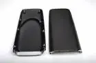
That is not v 2, more like v 5-6All I'm sayin... is that I hope you get G hood v.2 sorted out so I dont have to give you all the s hit back that you have me about cutting up a stock hood and not finishing it.
That is not v 2, more like v 5-6All I'm sayin... is that I hope you get G hood v.2 sorted out so I dont have to give you all the s hit back that you have me about cutting up a stock hood and not finishing it.

No, I've gotta plan for that.So @Davedacarpainter. Like I always do, I am sitting here thinking about the mismatch possibility between the front, and rear of the car because of the primered front pieces, and the painted rear ones. Do you think we'll have an issue here?
36 days. (More like 8 actual)

But imagine if they where set into the hood-like a slope down . They could even be sealed off . Idk lol no doubt you will find your best optionalready thought about that Chris,...I think that might be two G vents too many though.


After the hood, I'm gonna have to get the car running again. I now have a facility to paint the car in, and that'll require that it runs decently to be able to load it on a trailer, and move the thing around. I'm thinking that the hood will take me till next Thursday (if these patch panels don't completely pound me in the ass). That following Sunday, I'll have to finish a few things w/ the tank and lines, hook up the battery and restart it. It hunts and surges at idle until the WB takes control, once that happens though, the car settles into an 800 RPM idle. At least it did before all of this body work started.Hello Mike @Davedacarpainter told me I was summoned....... what can I program for you?
Okay going high is fine but the fan and the water pump are fairly large loads. Do these outputs trigger relays if so it's much easier to pull the relay to ground and then use the relay to feed the load. If the loads too large then the output will drop outAfter the hood, I'm gonna have to get the car running again. I now have a facility to paint the car in, and that'll require that it runs decently to be able to load it on a trailer, and move the thing around. I'm thinking that the hood will take me till next Thursday (if these patch panels don't completely pound me in the ass). That following Sunday, I'll have to finish a few things w/ the tank and lines, hook up the battery and restart it. It hunts and surges at idle until the WB takes control, once that happens though, the car settles into an 800 RPM idle. At least it did before all of this body work started.
It's that, and the fact that the spare output that comes from the relay board that is used to control the WP doesn't seem to work. It's connected to one of the 4 pins that were for the IAC, but I repurposed those in the build to use as outputs to control fan, and WP. The fan works, the WP pin is supposed to go high ((I think) I.E. have 12v,) but it doesn't. I have left the dash top off on purpose to enable access to the rats nest of wires and relays so that I can troubleshoot this, and I'd really like to solve it so I can put the top on, and be done with it.
There are relays involved, (the standard 4 pin 30A variety) Seemed that when I checked voltage on the suspect wire, that there is some weird amount there (like 10v) but, again didn't have the car running enough to actually troubleshoot it adequately back then. I am sending 12v to trigger both the relays for the fan, and the WP. I could just trigger both from the same trigger signal worse case scenario, but there are instances where I really want that pump off/on to help control the temp. (You may remember that this car doesn't seem to get hot when the pump runs continuously. Either I have too big a heater bypass going, or the T stat is stuck open, or it just wasn't hot enough outside (January) to allow the dumb assed thing to cycle.)Okay going high is fine but the fan and the water pump are fairly large loads. Do these outputs trigger relays if so it's much easier to pull the relay to ground and then use the relay to feed the load. If the loads too large then the output will drop out
The easier way would be to pull the relay to ground through the relay circuit don't use the high side drivers unless you have to. I found that the high side drivers can be problematic if you don't have the right resistor installed. An easier method of troubleshooting would be to set the parameter on the output 2 TPS that way you can just push the gas pedal and watch it come on. This way you don't even have to have the car running just turn the key to the Run positionThere are relays involved, (the standard 4 pin 30A variety) Seemed that when I checked voltage on the suspect wire, that there is some weird amount there (like 10v) but, again didn't have the car running enough to actually troubleshoot it adequately back then. I am sending 12v to trigger both the relays for the fan, and the WP. I could just trigger both from the same trigger signal worse case scenario, but there are instances where I really want that pump off/on to help control the temp. (You may remember that this car doesn't seem to get hot when the pump runs continuously. Either I have too big a heater bypass going, or the T stat is stuck open, or it just wasn't hot enough outside (January) to allow the dumb assed thing to cycle.)
So, again, if it turns out that the problem is one of the conditions above, and I fix that, I can blow off the second output, and combine the fan and WP on the one that works. All of that junk stay off until the engine reaches like 190, and then the magic happens, and they both come on and run till the engine drops to some other lower set temp.
I'm using a relay board. When I I said that the output was supposed to go " high" I just assumed that meant it was supposed to output 12v from the relay board. I don't remember zackly what was involved, but I wired in the appropriate jumpers on the Ecu to circumvent IAC control on the board, and repurpose them for what I'm using them for.The easier way would be to pull the relay to ground through the relay circuit don't use the high side drivers unless you have to. I found that the high side drivers can be problematic if you don't have the right resistor installed. An easier method of troubleshooting would be to set the parameter on the output 2 TPS that way you can just push the gas pedal and watch it come on. This way you don't even have to have the car running just turn the key to the Run position
It's OK we need time to sit and talk, give me a call sometime we will get ya worked out.I'm using a relay board. When I I said that the output was supposed to go " high" I just assumed that meant it was supposed to output 12v from the relay board. I don't remember zackly what was involved, but I wired in the appropriate jumpers on the Ecu to circumvent IAC control on the board, and repurpose them for what I'm using them for.
In reality there are so many things I have questions about that I couldn't get firm answers/ instruction from DIY it's a wonder the damn car even runs in the first place. The fast idle valve I'm using appears to be worthless, I don't think it affected the idle speed one hundred RPM when I'm cold start,... I have no clue if the boost control valve will work either as that was the same deal ( no difinitive directions as how to wire it)
I'm a mess.

Yes you can program the outputs to any number of parameters. The relays on this peticular unit (transistor) pull to ground. You can however build a (high side driver) using a few parts....Most automobile computers use current sink technology. They do not source power to any relay, solenoid or actuator like the IAC, fuel pump relay, or fuel injectors. Instead the computer provides a ground path for the positive battery voltage to get back to the battery negative terminal. That flow of power from positive to negative is what provides the energy to make the IAC, fuel pump relay, or fuel injectors work. No ground provided by the computer, then the actuators and relays don't operate.
This helps to protect the computer if a short to ground happens. Since it does not provide power, accidently grounding the computer output doesn't hurt anything. Power up the computer and get ready to test the output . Place one voltmeter lead on the output of a computer circuit and the other to ground. If you don't see any voltage over a few tenths of a volt, the computer is providing a ground. To prove this, use a test light with one connection to battery positive terminal and the other to the computer output under test. The next part is harder, figure some way to make the computer toggle the output. The stock Ford ECC is easy, you jumper it into test mode and turn on the ignition. I will assume that the computer you are using has a similar feature.