3g alt wiring questions. long with lots of pictures.

cenok is family

15 Year Member
Jun 25, 2003
1,409
69
79
Norman, Ok
this is kinda for verification purposes but here's whats going on. the other day my "AMP" light came on and my battery meter is down to like 8 when it's on. i work at autozone so i tested my alternator and battery, both came back good. well i knew my 3g wiring was in question so i researched some more, read Rolands "3g alt: a how to" thread and redid it all. here's what i've done so far:

i re-ran a 4g power wire from the alt post, across the front of the radiator, under the battery tray, into a 200A ANG style fuse, then onto the solonoid.
View attachment 359632
View attachment 359634

i completely tore out the old alternator power wire and saw it shared a fuse link with a yellow wire that also went to the 3 wire plug on the alternator. (see last pic, yellow wire circled in blue) so i clipped the yellow wire after the factory ford fusable link and ran it to the the 200A ANG fuse in my 4g power wire. it's the wire i'm holding in my finger.
View attachment 359636

reading a bunch of the "how to's" on this site and many others, i've gathered that the stator wire for the 3g alt is the small white w/black stripe wire in the middle of the 3 wire "D" shaped plug that i ran to the alternator. is this correct? (pic is in the middle of me soldering it together)
View attachment 359638

here's what the wiring for the "D" shaped plug is. the yellow wire is running to the 200A fuse, the green one i didn't touch, and the white one is now my stator wire. is this correct?
View attachment 359640

View attachment 359641

so did i do this all correct? thank a ton guys
 
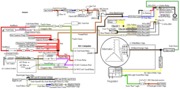
Check out the diagram: the yellow wire is the same in both places. It has a fuse link in it to protect the circiut.

Diagram courtesy of Tmoss & Stang&2birds
fuel-alt-links-ign-ac.gif


See the following website for some help from Tmoss (diagram designer) & Stang&2Birds (website host) for help on 88-95 wiring http://www.veryuseful.com/mustang/tech/engine/ Everyone should bookmark this site.

Ignition switch wiring
http://www.veryuseful.com/mustang/tech/engine/images/IgnitionSwitchWiring.gif

Fuel, alternator, A/C and ignition wiring
http://www.veryuseful.com/mustang/tech/engine/images/fuel-alt-links-ign-ac.gif

Complete computer, actuator & sensor wiring diagram for 88-91 Mass Air Mustangs
http://www.veryuseful.com/mustang/tech/engine/images/88-91_5.0_EEC_Wiring_Diagram.gif

Vacuum diagram 89-93 Mustangs
http://www.veryuseful.com/mustang/tech/engine/images/mustangFoxFordVacuumDiagram.jpg

HVAC vacuum diagram
http://www.veryuseful.com/mustang/tech/engine/images/Mustang_AC_heat_vacuum_controls.gif

TFI module differences & pinout
http://www.veryuseful.com/mustang/tech/engine/images/TFI_5.0_comparison.gif

Fuse box layout
http://www.veryuseful.com/mustang/tech/engine/images/MustangFuseBox.gif
 

Attachments

  • fuel-alt-links-ign-ac.gif
    fuel-alt-links-ign-ac.gif
    83.1 KB · Views: 309
The Yellow wire should be ok. It's a remote voltage sensing circuit. It compares what the alt is putting out vs what the battery (via the starter solenoid's battery lug) is reading. Say your solenoid lug is reading 1/2 volt lower than the alt's output voltage, the regulator bumps up the output to accomodate this.

The way you have it should be fine - just ensure your charge cable stays in good shape (you can even just loop that sense wire from the regulator plug to the charge cable).

You're correct about the stator wire. It just loops from the regulator plug to the single terminal in the 3G housing.

AFAI can tell, you did it right. :nice:
 
maybe this will help unless you got it working. it doesn't show the 4awg wire, but you already know about it. i forget where i got the pic.

99a89284.gif

It seems as though there are 2 ways you can do it, I see you show it with hooking the Orange/Black Wires up, but I also know of leaving them disconnected and just having the 4G Power Wire. I am not sure if there is any pros or cons to doing it either way.
 

Attachments

  • 99a89284.gif
    99a89284.gif
    77 KB · Views: 2,221
It seems as though there are 2 ways you can do it, I see you show it with hooking the Orange/Black Wires up, but I also know of leaving them disconnected and just having the 4G Power Wire. I am not sure if there is any pros or cons to doing it either way.

The safest way is to use an adequate new power cable (as a reasonable length of 4 gauge cable is for a 130 amp alt) and not reconnect the stock power wires to the 3G.

If the 4 gauge cable blows the fuse or a terminal falls off (etc), then all the current will be trying to make it through the stock wires. You had better hope that the fusible links blow before the harness catches on fire (and considering that the links have not blown in time with 2G alts, that's not a good bet to take).

Reusing the stock charge wires comes down to being an unnecessary risk.
 
I need to unhook my orange/black wires:bang:

JT, when I was meeting with Kevin (04Sleeper), he seen that I had connected the black/orange wires back up, and he said, you "would have a fit" if you seen that, and he didn't recommend it either:)

I believe it is what the Paperformance instructions showed, but we all know how that is.

I'm glad I seen this thread, because it reminded me, better safe than sorry:nice:

So can I just disconnect them, and pull them out of the way?
 
I need to unhook my orange/black wires:bang:

JT, when I was meeting with Kevin (04Sleeper), he seen that I had connected the black/orange wires back up, and he said, you "would have a fit" if you seen that, and he didn't recommend it either:)

I believe it is what the Paperformance instructions showed, but we all know how that is.

I'm glad I seen this thread, because it reminded me, better safe than sorry:nice:

So can I just disconnect them, and pull them out of the way?

yeah but the yellow wire coming off the 'D' shaped plug is tied in with the old power wire right before the solonoid. just cut it after the fusable link and splice it into the new power wire like in this picture.

View attachment 359190
 
Or you can loop the wire leaving the A port of the regulator to the charge stud on the back of the alternator. That wire needs to see battery voltage (where it sees this is the choice of the owner. If it's *not* remote, just ensure your charge cable is in impeccable shape).

David, that's funny about your meeting with Kevin. :nice: I'm surprised my name ever came up (who wants to ruin a meet-n-greet by bringing me up. :D ).

FWIW, someone once asked PA-P why they recommend wiring it like that and IIRC (don't quote me on this) it was to accomodate all the different alternator outputs.

I still would never use more than one power cable myself (even if I had a 200 amp alt, I'd run one fatty cable and one fuse and call it good).
 
In looking at what is here, I dont see what the need is of what you did with the Yellow Wire?

The yellow wire (sense circuit) needs to see battery voltage one way or another. He's kept the wire remotely located the way he did it.

IIRC, the wire in OEM form is connected on the alt side of the circuit protection (the alt sees this circuit fall to 0 volts if the link for the charge cable blows).
 
In looking at what is here, I dont see what the need is of what you did with the Yellow Wire?

yeah what hissin said. originally, the yellow wire is spliced into the original power wire, right before it connects to the solonoid. when i disconnected the old power wire and ran a new 4ga power wire, that yellow wire was still spliced into the old, unused power wire so it was getting an incorrect reading. just gotta splice it back into the new power wire somewhere. the way i did it was just easiest for me.

Maybe I missed it in the previous postsbut don't forget to upgrade the ground at the Fenderwell to 4 ga too! There's a pic on here some place. Maybe it was a Jrichker post.

yeah i did. i left the factory braided ground strap there and added a new 4ga one where jrichker said to...from the fenderwell by the battery to my A/C compressor bracket.
 
I need to unhook my orange/black wires:bang:

JT, when I was meeting with Kevin (04Sleeper), he seen that I had connected the black/orange wires back up, and he said, you "would have a fit" if you seen that, and he didn't recommend it either:)

I believe it is what the Paperformance instructions showed, but we all know how that is.

I'm glad I seen this thread, because it reminded me, better safe than sorry:nice:

So can I just disconnect them, and pull them out of the way?
David, I encourage you, (Actually Anyone), to trace the 2 Orange/Black wires back into the harness. Undo all the electrical tape and such and see where the 2 wires are spliced into 1!!! :shock: I am not certain why Ford did it this way but you will understand after that point just by seeing it first hand.

It is when you see the poor connection of the 2 into 1 that you will truly appreciate upgrading the wiring. :nice:

And JT, you are always a good conversation piece will all your knowledge. ;)