No Crank checklist for 5.0 Mustangs
Revised 24-Oct-2013 to update voltage drop figures.
No crank, slow crank and stuck starter solenoid problems have the same root causes – low battery voltage and poor connections. For that reason, they are grouped together.
Use the same initial group of tests to find the root cause of slow crank, no crank and stuck solenoid problems.
Since some of the tests will bypass the safety interlocks, make sure that the car is in neutral and the parking brake is set. Becoming a pancake isn’t part of the repair process…
1.) Will the car start if it is jumped? Then clean battery terminals and check battery for low charge and dead cells. A good battery will measure 12-13 volts at full charge with the ignition switch in the Run position but without the engine running.
A voltmeter placed across the battery terminals should show a minimum of 9.5-10 volts when the ignition switch is turned to the Start position and the starter engages or tries to engage. Less than this will result in a clicking solenoid, or slow cranking (if it cranks at all) or a starter solenoid that sticks and welds the contacts together.
Most auto parts stores will check your battery for free. It does not have to be installed in the car to have it checked; you can carry it with you to the auto parts store.
The battery posts and inside of the battery post terminals should be scraped clean with a knife or battery post cleaner tool. This little trick will fix a surprising number of no start problems.
The clamp on with 2 bolts battery terminal ends are a known problem causer. Any place you see green on a copper wire is corrosion. Corrosion gets in the clamped joint and works its way up the wire under the insulation. Corroded connections do not conduct electricity well. Avoid them like the plague...
If the starter solenoid welds the contacts, then the starter will attempt to run anytime there is power in the battery. The cables and solenoid will get very hot, and may even start smoking. The temporary fix for a welded starter solenoid is to disconnect the battery and smack the back of the solenoid housing a sharp blow with a hammer. This may cause the contacts to unstick and work normally for a while.
A voltmeter is handy if you are familiar with how to use it to find bad connections. Measure the voltage drop across a connection while trying to start the car: more than .25 volts across a connection indicates a problem. The voltage drop tests need to be done while cranking the engine. It's the current flowing through a connection or wire that causes the voltage drop.
See http://assets.fluke.com/appnotes/automotive/beatbook.pdf for help for help troubleshooting voltage drops across connections and components. .
Voltage drops should not exceed the following:
200 mV Wire or cable
300 mV Switch or solenoid
100 mV Ground
0.0V Connections
A voltage drop lower that spec is always acceptable.
2.) Check the battery to engine block ground down near the oil filter, and the ground behind the engine to the firewall. All grounds should be clean and shiny. Use some sandpaper to clean them up.
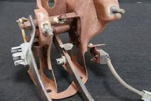
3.) Jump the big terminals on the starter solenoid next to the battery with a screwdriver - watch out for the sparks! If the engine cranks, the starter and power wiring is good. The starter relay is also known as a starter solenoid.
The rest of the tech note only concerns no crank problems. If your problem was a stuck solenoid, go back to step 1.
4.) Then pull the small push on connector (small red/blue wire) off the starter solenoid (Looks like it is stuck on a screw). Then jump between the screw and the terminal that is connected to the battery. If it cranks, the relay is good and your problem is in the rest of the circuit.
5.) Remember to check the ignition switch, neutral safety switch on auto trans and the clutch safety switch on manual trans cars. If they are good, then you have wiring problems.
Typical start circuit...
Diagram courtesy of Tmoss & Stang&2birds
6.) Pull the starter and take it to AutoZone or Pep Boys and have them test it. Starter fails test, then replace it. If you got this far, the starter is probably bad.
Starter solenoid wiring for 86-91 Mustang
Starter solenoid wiring 92-93 Mustang or earlier Mustang with upgraded high torque mini starter.
Electrical checks for the switches and starter solenoid
Remove the small red/blue wire from the starter solenoid. Use a screwdriver to bridge the connection from the battery positive connection on the starter solenoid to the small screw where the red/blue wire was connected. The starter should crank the engine. If it does not, the starter solenoid is defective or the battery lacks sufficient charge to crank the engine.
If the starter does crank the engine, the problem is in the clutch safety circuit (5 speed) or Neutral Sense Switch (auto trans) or ignition switch.
See the Typical start circuit diagram above for wiring information for troubleshooting.
You will need a voltmeter or test lamp for the rest of the checks. Connect one lead of the voltmeter or test lamp to ground. The other lead will connect to the item under test.
Look for 12 volts on the white/pink wire when the ignition switch is turned to the Start position. Check the ignition switch first.
No 12 volts, replace the ignition switch.
The next step will require you to push the clutch pedal to the floor (5 speed) or put the transmission in neutral (auto trans) while the ignition switch is turned to the Start position.
Good 12 volts, check the clutch safety switch (5 speed) or Neutral Sense Switch (auto trans) for good 12 volts on both sides of the switches. No 12 volts on both sides of the switch and the switches are defective or out of adjustment. Check the wiring for bad connections while you are at it.
Dump the codes: Codes may be present even if the Check Engine Light (CEL) isn't on.
Dumping the computer diagnostic codes on 86-95 Mustangs
Revised 26-July-2011. Added need to make sure the clutch is pressed when dumping codes.
Codes may be present even if the check engine light hasn’t come on, so be sure to check for them.
Here's the way to dump the computer codes with only a jumper wire or paper clip and the check engine light, or test light or voltmeter. I’ve used it for years, and it works great. You watch the flashing test lamp or Check Engine Light and count the flashes.
Post the codes you get and I will post 86-93 model 5.0 Mustang specific code definitions and fixes. I do not have a complete listing for 94-95 model 5.0 Mustangs at this time.
Be sure to turn off the A/C, and put the transmission in neutral when dumping the codes. On a manual transmission car, be sure to press the clutch to the floor.
Fail to do this and you will generate a code 67 and not be able to dump the Engine Running codes.
If your car is an 86-88 stang, you'll have to use the test lamp or voltmeter method. There is no functional check engine light on the 86-88's except possibly the Cali Mass Air cars.
The STI has a gray connector shell and a white/red wire. It comes from the same bundle of wires as the self test connector.
89 through 95 cars have a working Check Engine light. Watch it instead of using a test lamp.
The STI has a gray connector shell and a white/red wire. It comes from the same bundle of wires as the self test connector.
WARNING!!! There is a single dark brown connector with a black/orange wire. It is the 12 volt power to the under the hood light. Do not jumper it to the computer test connector. If you do, you will damage the computer.
What to expect:
You should get a code 11 (two single flashes in succession). This says that the computer's internal workings are OK, and that the wiring to put the computer into diagnostic mode is good. No code 11 and you have some wiring problems.
This is crucial: the same wire that provides the ground to dump the codes provides signal ground for the TPS, EGR, ACT and Map/Baro sensors. If it fails, you will have poor performance, economy and driveablity problems
Some codes have different answers if the engine is running from the answers that it has when the engine isn't running. It helps a lot to know if you had the engine running when you ran the test.
Dumping the Engine Running codes: The procedure is the same, you start the engine with the test jumper in place. Be sure the A/C is off, and clutch (if present) is pressed to the floor, and the transmission is in neutral. You'll get an 11, then a 4 and the engine will speed up to do the EGR test. After the engine speed decreases back to idle, it will dump the engine running codes.
Trouble codes are either 2 digit or 3 digit, there are no cars that use both 2 digit codes and 3 digit codes.
Your 86-88 5.0 won't have a working Check Engine Light, so you'll need a test light.
See AutoZone Part Number: 25886 , $10
Alternate methods:
For those who are intimidated by all the wires & connections, see
Actron® for what a typical hand scanner looks like. Normal retail price is about $30 or so at AutoZone or Wal-Mart.
Or for a nicer scanner see
www.midwayautosupply.com/Equus-Digital-Ford-Code-Reader/dp/B000EW0KHW Equus - Digital Ford Code Reader (3145It has a 3 digit LCD display so that you don’t have to count flashes or beeps.. Cost is $22-$36.
Computer will not go into diagnostic mode on 86-90 model 5.0 Mustangs
Disconnect the battery positive terminal before making any resistance checks.
The voltage drop in the ground cable will cause incorrect resistance readings.
How it is supposed to work:
The black/white wire (pin 46) is signal ground for the computer. It provides a dedicated ground for the EGR, Baro, ACT, ECT, & TPS sensors as well as the ground to put the computer into self test mode.
If this ground is bad, none of the sensors mentioned will work properly. That will severely affect the car's performance. You will have hard starting, low power and drivability problems. Since it is a dedicated ground, it passes through the computer on its way to the computer main power ground that terminates at the battery pigtail ground. It should read less than 1.5 ohms when measured from anyplace on the engine harness with the battery pigtail ground as the other reference point for the ohmmeter probe.
What sometimes happens is that the test connector black/white wire gets jumpered to power which either burns up the wiring or burns the trace off the pc board inside the computer. That trace connects pins 46 to pins 40 & 60.
The STI (Self Test Input ) is jumpered to ground to put the computer into test mode. Jumpering it to power can produce unknown results, including damage to the computer. The ohm test simply verifies that there are no breaks in the wiring between the test connector and the computer input.
How to test the wiring :
With the power off, measure the resistance between the computer test ground (black/white wire) on the self test connector and battery ground. You should see less than 1.5 ohms.
If that check fails, remove the passenger side kick panel and disconnect the computer connector. There is a 10 MM bolt that holds it in place. Measure the resistance between the black/white wire and pin 46 on the computer wiring connector: it should be less than 1.5 ohms. More that 1.5 ohms is a wiring problem. If it reads 1.5 ohms or less, then the computer is suspect. On the computer, measure the resistance between pin 46 and pins 40 & 60: it should be less than 1.5 ohms. More that that and the computer’s internal ground has failed, and the computer needs to be repaired or replaced.
See
http://www.stangnet.com/mustang-forums/749974-computer-issue.html#post7490537 for Joel5.0’s fix for the computer internal signal ground.
If the first ground check was good, there are other wires to check. Measure the resistance between the STI computer self test connector (red/white wire) and pin 48 on the computer main connector: it should be less than 1.5 ohms. More that 1.5 ohms is a wiring problem
The following is a view from the computer side of the computer wiring connector: it is for an A9L, A9P computer.
Diagram courtesy of Tmoss & Stang&2birds
Check out the diagram and notice all the places the black/white wire goes. Almost every sensor on the engine except the MAF is connected to it.
See the following website for some help from Tmoss (diagram designer) & Stang&2Birds
(website host) for help on 88-95 wiring
http://www.veryuseful.com/mustang/tech/engine
See the graphic for the 10 pin connector circuit layout.