Engine 90 5.0 LX hesitation under acceleration

New to this forum so I’m sorry if I posted in the wrong spot.

I will try to be as detailed as I can...

I have a 90 foxbody LX 302 with “slight mods” reason it is captioned is because the guy I bought it from didn’t know what has been done besides it having a cam. Once I got the car I did the normal tune-up with new brakes, spark plugs, wires, oil, oil filter, and bought a new MSD distributor cap and rotor. Anyway the car was running fine till it started to pop under acceleration; the car did have some backfire at high RPM when off the throttle. I checked the codes and only came up with a bad EGR valve, and a fault 02 sensor. Checked the O2 sensors and one had a cut wire that I fixed and cleared the code up. I tried to use a timing light and rotate the distributor thinking this would clear up the popping under acceleration. Timing showed a retard degree of 10 so I slowly advanced to BTC of 10 degrees which is what the manual called for. This helped a lot and was able to drive for about a month. Till an exhaust leak arose and found that what ever the previous owner did to plug the “thermoreactor pipe”, smog pipe off the rear of the heads, decided to blow off.

Hurricane Florence hit and the car sat till today which I bought plugs and closed up the exhaust leak.

Went for for a drive and noticed that at idle I was barely at 500 RPM and struggling to not stall. I have to over accelerate to not stall to get moving and once going I can feel a lack of power as if not getting enough fuel then all of a sudden the car would surge as if all the fuel built up then decided to slam into the engine.

I cleaned up the 10pin connections which got the idle rpm back to normal.

Drove fine for about 10 miles then started to act up. when I give throttle it hesitates then catches up then hesitates. Sometimes it will bog down and or somethings it’ll just pick up and drive along.

i should also mention that I feel a decent amount of power loss.

Ran the code reader again and got the following codes

KOEO
67 AC input high= which I think may be from the AC Removal from the previous owner
KOER
41 HEGO (HO2S) sensor voltage low/ system lean
91 HEGO (HO2S) sensor voltage low/ system lean
I believe 41 means passenger side and 91 means drivers

33 EGR valve not opening properly
Any ideas how to solve these codes? And if by fixing them do they seem trike they will fix my issues?
 
  • Sponsors (?)


Welcome to stangnet, you have a jump on resolving these issues, now I think you need to find what your fuel pressure is, also check all vacuum lines for cracks or loose connections. It's tough to deal with someone else's modifications like the unknown type of cam, here in the tech threads is the 5.0 tech/how to section, in there look for the surging idle checklist, I know some of this stuff you have done already but it will show you how to check things and what to do when you find a problem so start at the top and work your way through step by step even if you have done something already, the next step will depend on the results of the one before, keep us posted, we can help you along the way. It also would be helpful to post a pic of the engine so maybe we can spot something your missing.
Most problems are from vacuum leaks and improper procedures.
 
Code 41 or 91. Or 43 Three digit code 172 or 176 - O2 sensor indicates system lean. Look for a vacuum leak or failing O2 sensor.

Revised 24 Aug 2018
1.) To correct the RH & LH mismatch on 91-93 5.0 Mustangs
2.) To add Tmoss’ wiring diagrams for 88-95 Mustangs


Code 41 is the passenger side sensor, as viewed from the driver's seat.
Code 91 is the driver side sensor, as viewed from the driver's seat.

Code 172 is the passenger side sensor as viewed from the driver's seat.
Code 176 is the driver side sensor, as viewed from the driver's seat.

Code 43 is not side specific according to the Probst Ford Fuel injection book.

The computer sees a lean mixture signal coming from the O2 sensors and tries to compensate by adding more fuel. Many times the end result is an engine that runs pig rich and stinks of unburned fuel.

The following is a Quote from Charles O. Probst, Ford fuel Injection & Electronic Engine control:

"When the mixture is lean, the exhaust gas has oxygen, about the same amount as the ambient air. So the sensor will generate less than 400 Millivolts. Remember lean = less voltage.
When the mixture is rich, there's less oxygen in the exhaust than in the ambient air , so voltage is generated between the two sides of the tip. The voltage is greater than 600 millivolts. Remember rich = more voltage.
Here's a tip: the newer the sensor, the more the voltage changes, swinging from as low as 0.1 volt to as much as 0.9 volt. As an oxygen sensor ages, the voltage changes get smaller and slower - the voltage change lags behind the change in exhaust gas oxygen.

Because the oxygen sensor generates its own voltage, never apply voltage and never measure resistance of the sensor circuit. To measure voltage signals, use an analog voltmeter with a high input impedance, at least 10 megohms. Remember, a digital voltmeter will average a changing voltage." End Quote

Testing the O2 sensors 87-93 5.0 Mustangs

Measuring the O2 sensor voltage at the computer will give you a good idea of how well they are working. You'll have to pull the passenger side kick panel off to gain access to the computer connector. Remove the plastic wiring cover to get to the back side of the wiring. Use a safety pin or paper clip to probe the connections from the rear.


Disconnect the O2 sensor from the harness and use the body side O2 sensor harness as the starting point for testing. Do not measure the resistance of the O2 sensor, you may damage it. Resistance measurements for the O2 sensor harness are made with one meter lead on the O2 sensor harness and the other meter lead on the computer wire or pin for the O2 sensor.
Computer wiring harness connector, computer side.
88243.gif


Backside view of the computer wiring connector:
a9x-series-computer-connector-wire-side-view-gif.gif


87-90 5.0 Mustangs:
Computer pin 43 Dark blue/Lt green – LH O2 sensor
Computer pin 29 Dark Green/Pink – RH O2 sensor

The computer pins are 29 (RH O2 with a dark green/pink wire) and 43 (LH O2 with a dark blue/lt green wire). Use the ground next to the computer to ground the voltmeter. The O2 sensor voltage should switch between .2-.9 volt at idle.


91-93 5.0 Mustangs:
Computer pin 43 Red/Black – LH O2 sensor
Computer pin 29 Gray/Lt blue – RH O2 sensor

The computer pins are 29 (RH O2 with a Gray/Lt blue wire) and 43 (LH O2 with a Red/Black wire). Use the ground next to the computer to ground the voltmeter. The O2 sensor voltage should switch between .2-.9 volt at idle.


94-95 5.0 Mustangs; note that the 94-95 uses a 4 wire O2 sensor.
The computer pins are 29 (LH O2 with a red/black wire) and 27 (RH O2 with a gray/lt blue wire). Use pin 32 (gray/red wire) to ground the voltmeter. . The O2 sensor voltage should switch between .2-.9 volt at idle.


Note that all resistance tests must be done with power off. Measuring resistance with a circuit powered on will give false readings and possibly damage the meter. Do not attempt to measure the resistance of the O2 sensors, it may damage them.

Testing the O2 sensor wiring harness
Most of the common multimeters have a resistance scale. Be sure the O2 sensors are disconnected and measure the resistance from the O2 sensor body harness to the pins on the computer. Using the Low Ohms range (usually 200 Ohms) you should see less than 1.5 Ohms.


87-90 5.0 Mustangs:
Computer pin 43 Dark blue/Lt green – LH O2 sensor
Computer pin 29 Dark Green/Pink – RH O2 sensor
Disconnect the connector from the O2 sensor and measure the resistance:
From the Dark blue/Lt green wire in the LH O2 sensor harness and the Dark blue/Lt green wire on the computer pin 43
From the Dark Green/Pink wire on the RH O2 sensor harness and the Dark Green/Pink wire on the computer pin 29


91-93 5.0 Mustangs:
Computer pin 43 Red/Black – LH O2 sensor
Computer pin 29 Gray/Lt blue – RH O2 sensor
Disconnect the connector from the O2 sensor and measure the resistance:
From the Red/Black wire in the LH O2 sensor harness and the Red/Black wire on the computer pin 43
From the Gray/Lt blue wire on the RH O2 sensor harness and the Gray/Lt blue wire on the computer pin 29

94-95 5.0 Mustangs:
Computer pin 29 Red/Black – LH O2 sensor
Computer pin 27 Gray/Lt blue – RH O2 sensor
From the Red/Black wire in the LH O2 sensor harness and the Red/Black wire on the computer pin 29
From the Dark Green/Pink Gray/Lt blue wire on the RH O2 sensor harness and the Gray/Lt blue wire on the computer pin 27


There is a connector between the body harness and the O2 sensor harness. Make sure the connectors are mated together, the contacts and wiring are not damaged, and the contacts are clean and not coated with oil.

The O2 sensor ground (orange wire with a ring terminal on it) is in the wiring harness for the fuel injection wiring. I grounded mine to one of the intake manifold bolts

Check the fuel pressure – the fuel pressure is 37-41 PSI with the vacuum disconnected and the engine idling. Fuel pressure out of range can cause the 41 & 91 codes together. It will not cause a single code, only both codes together.

Make sure you have the proper 3 wire O2 sensors. Only the 4 cylinder cars used a 4 wire sensor, which is not compatible with the V8 wiring harness. The exception is that the 94-95 uses a 4 wire O2 sensor.

Replace the O2 sensors in pairs if replacement is indicated. If one is weak or bad, the other one probably isn't far behind.

Code 41 can also be due to carbon plugging the driver’s side Thermactor air crossover tube on the back of the engine. The tube fills up with carbon and does not pass air to the driver’s side head ports. This puts an excess amount of air in the passenger side exhaust and can set the code 41. Remove the tube and clean it out so that both sides get good airflow: this may be more difficult than it sounds. You need something like a mini rotor-rooter to do the job because of the curves in the tube. Something like the outer spiral jacket of a flexible push-pull cable may be the thing that does the trick.

If you get only code 41 and have changed the sensor, look for vacuum leaks. This is especially true if you are having idle problems. The small plastic tubing is very brittle after many years of the heating it receives. Replace the tubing and check the PVC and the hoses connected to it.

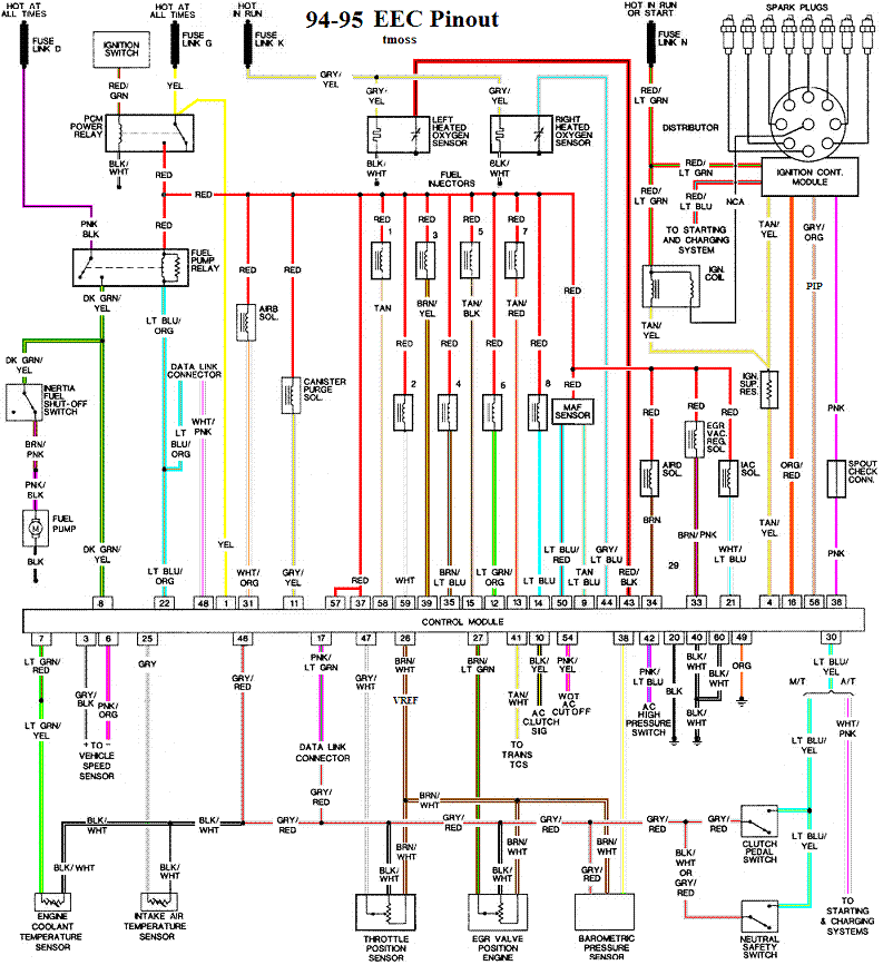
Complete computer, actuator & sensor wiring diagram for 94-95 Mustangs
94-95_5.0_EEC_Wiring_Diagram.gif


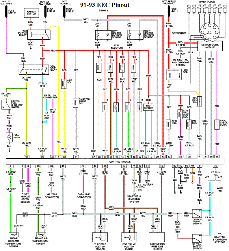
Complete computer, actuator & sensor wiring diagram for 91-93 Mass Air Mustangs
91-93_5.0_EEC_Wiring_Diagram.gif


Complete computer, actuator & sensor wiring diagram for 88-90 Mass Air Mustangs
88-91_5.0_EEC_Wiring_Diagram.gif


Code 67
Revised 18-Mar-2017 to include warning about the necessity of having a 5 speed O2 Sensor wiring harness when bypassing the wiring for test purposes

Cause of problem:
Clutch not depressed (5 speed) or car not in neutral (5 speed and auto) or not in park (auto) or A/C in On position when codes where dumped. Possible neutral safety switch or wiring problem. This code will prevent you from running the Key On Engine On tests.

External evidence from other sources claims that a code 67 can cause an idle surge condition. Do try to find and fix any issues with the switch and wiring if you get a code 67.

What the NSS (Neutral Safety Switch) does:
5 speed transmission: It has no connection with the starter, and the engine can be cranked without it being connected.
Auto transmission: It is the safety interlock that prevents the starter from cranking the engine with the transmission in gear.
What it does for both 5 speed and auto transmission cars:
The computer wants to make sure the A/C is off due to the added load on the engine for the engine running computer diagnostic tests. It also checks to see that the transmission is in Neutral (5 speed and auto transmission) and the clutch depressed (T5, T56, Tremec 3550 & TKO)). This prevents the diagnostics from being run when the car is driven. Key On Engine Running test mode takes the throttle control away from the driver for several tests. This could prove hazardous if the computer was jumpered into test mode and then driven.

The following is for 5 speed cars only. Do not do this unless you are sure that you have a 5 speed O2 Sensor harness!!!! Smoke, sparks and expensive pain in the wallet may ensue if you don’t.
The NSS code 67 can be bypassed for testing. You will need to temporarily ground computer pin 30 to the chassis. Computer pin 30 uses a Lt blue/yellow wire. Remove the passenger side kick panel and then remove the plastic cover from the computer wiring connector. Use a safety pin to probe the connector from the rear. Jumper the safety pin to the ground near the computer.
Be sure to remove the jumper BEFORE attempting to drive the car!!!

a9x-series-computer-connector-wire-side-view-gif.71316
 
Didn’t mean to repeat some images.
I took them apart and thoroughly cleaned it all out. Still no change.
Followed the surge checklist and got to the MAF disconnect while running and noticed the cars idle changed dramatically. Decided to give it a bit of throttle while it was disconnected and it was way better. Felt the power come back as well.
I had just replaced the MAF 2 months ago and still had a warranty so I swapped it for a new one and no fix.
Does this mean I have a faulty connector?

Posted the engine bay for General karthief.
 
I have a 90 foxbody LX 302 with “slight mods” reason it is captioned is because the guy I bought it from didn’t know what has been done besides it having a cam./QUOTE]

The car probably doesn't have a cam swap done to it. From your pictures it looks pretty stock unless you have a receipt saying different I'd assume it is stock. Looking at your pics I see the following modifications :

dodge intrepid dual efan
cold air intake
ac delete
power steering pump relocation
heater core by passed
silicone radiator hose kit
msd plug wires
march adjustable alt bracket
3 core radiator
radiator hold down
thermostate housing looks newer so most likely a colder temp tstat

I'd definitely replace that egr sensor
 
For MAF problems, follow the test path below...


Code 66 or 157 MAF below minimum test voltage.

Revised 15 mar 2018 to clarify how to do resistance checks on the MAF wiring

Insufficient or no voltage from MAF. Dirty MAF element, bad MAF, bad MAF wiring, missing power to MAF. Check for missing +12 volts on this circuit. Check the two links for a wiring diagram to help you find the red wire for computer power relay switched +12 volts. Check for 12 volts between the red and black wires on the MAF heater (usually pins A & B). while the connector is plugged into the MAF. This may require the use of a couple of safety pins to probe the MAF connector from the back side of it.

Computer wiring harness connector, wire side
71316.gif


Computer wiring harness connector, computer side side
88243.gif


Diagrams courtesy of Tmoss and Stang&2Birds

ECC Diagram for 88-90 5.0 Mustangs
88-91_5.0_EEC_Wiring_Diagram.gif


ECC Diagram for 91-93 5.0 Mustangs
91-93_5.0_EEC_Wiring_Diagram.gif


94-95 Diagram for 94-95 5.0 Mustangs[/b]
94-95_5.0_EEC_Wiring_Diagram.gif


How the MAF works

There are three parts in a MAF: the heater, the sensor element and the amplifier. The heater heats the MAF sensor element causing the resistance to increase. The amplifier buffers the MAF output signal and has a resistor that is laser trimmed to provide an output range compatible with the computer's load tables. Changes in RPM causes the airflow to increase or decrease, changing the voltage output.. The increase of air across the MAF sensor element causes it to cool, allowing more voltage to pass and telling the computer to increase the fuel flow. A decrease in airflow causes the MAF sensor element to get warmer, decreasing the voltage and reducing the fuel flow.

The MAF element is secured by 2 screws & has 1 wiring connector. To clean the element, remove it from the MAF housing and spray it down with electronic parts cleaner or non-inflammable brake parts cleaner (same stuff in a bigger can and cheaper too).

89-90 Model cars: Measure the MAF output at pins C & D on the MAF connector (dark blue/orange and tan/light blue) or at pins 50 & 9 on the computer. Be sure to measure the sensor output by measuring across the pins and not between the pins and ground.

91-95 Model cars: Measure the MAF output at pins C & D on the MAF connector light blue/red and tan/light blue) or at pins 50 & 9 on the computer. Be sure to measure the sensor output by measuring across the pins and not between the pins and ground.


At idle = approximately .6 volt
20 MPH = approximately 1.10 volt
40 MPH = approximately 1.70 volt
60 MPH = approximately 2.10 volt

Actually MAF pins C & D float with reference to ground. The signal output of the MAF is a differential amplifier setup. Pins C & D both carry the output signal, but one pin's output is inverted from the other. The difference in signal between C & D is what the computer's input circuit is looking for. The difference in the two outputs helps cancel out electrical noise generated by the ignition system and other components. Since the noise will be of the same polarity, wave shape and magnitude, the differential input of the computer electronically subtracts it from the signal. Then it passes the signal on to an Analog to Digital converter section inside the computer's CPU chip.


Check the resistance of the MAF signal wiring
For the next 2 checks make your measurement with the MAF disconnected from the wiring harness.

Pin D on the MAF wiring harness and pin 50 on the computer (dark blue/orange wire) should be less than 2 ohms. Pin C on the MAF wiring harness and pin 9 on the computer (tan/light blue wire) should be less than 2 ohms.

There should be a minimum of 10K ohms between either pin C or D on the MAF wiring connector and pins A or B.

Reconnect the MAF to the wiring harness and proceed to the next section.

See the following website for some help from Tmoss (diagram designer) & Stang&2Birds (website host) for help on 88-95 wiring http://www.veryuseful.com/mustang/tech/engine/

Ignition switch wiring
http://www.veryuseful.com/mustang/tech/engine/images/IgnitionSwitchWiring.gif

Fuel pump, alternator, ignition & A/C wiring
http://www.veryuseful.com/mustang/tech/engine/images/fuel-alt-links-ign-ac.gif

Computer,. actuator & sensor wiring
http://www.veryuseful.com/mustang/tech/engine/images/88-91_5.0_EEC_Wiring_Diagram.gif

Fuse panel layout
http://www.veryuseful.com/mustang/tech/engine/images/MustangFuseBox.gif

Vacuum routing
http://www.veryuseful.com/mustang/tech/engine/images/mustangFoxFordVacuumDiagram.jpg
 
So I spent the day working on the surge idle checklist. Here’s what I got
Pulled codes
KOEO: 11
KOER: 41, 91, 33
Went to the parts store and got a new EGR valve to test if it would clear up code 33 but it didn’t not.Returned the part since it was $85 that I didn’t really need to spend.
Then I started on the decision tree to test all computer related issues.
Car was warmed up and running when I disconnected the IAB,no change, then disconnected the MAF, idle slowed and lowered; throttle response improved greatly as in no more hesitation. Then disconnected the spout, idle picked up but I know you can’t run the car that way. I disconnected everything in order as per the decision tree and once one was disconnected I left it that way then moved to the next sensor.
I wanted to test the MAF for voltage again but didn’t have a multimeter to test with today.
Wasn’t able to afford a fuel pressure gauge have to wait till payday.
While I was checking for vacuum leaks I found a line and I have no idea where it goes. I looked up vacuum diagrams but no luck.
It appears to come off the EGR Vac regulator. But it’s not the line that goes to the EGR or to the VCV. Any ideas? It’s located on the passenger side of the engine bay and has a red wire and a green wire go into what I assume is the EGR Vac regulator then it splits into 4 ports 1 empty, and the other 3 have lines coming out. 1 to the EGR, 1 going to the VCV, and the last one is the broken one.
 
Ran the multimeter on the MAF connector
Red wire and black(A&B) = 12.56v
C & D= 4.56v at idle which is way too high
I then check resistance(ohms) between all pins and got no measurement as in my multimeter counts find any resistance.
Which is bad right?
What do I do now?
 
Ran the multimeter on the MAF connector
Red wire and black(A&B) = 12.56v
C & D= 4.56v at idle which is way too high
I then check resistance(ohms) between all pins and got no measurement as in my multimeter counts find any resistance.
Which is bad right?
What do I do now?
Replace the MAF if you are positive that your C & D= 4.56v at idle reading is correct.