Alt wiring Q's jrichker and wiring gurus come in!

Is it possible to wire a standard 2g or 3g alt so it works like or similar to a 1 wire alt? Im trying to avoid spending extra dollars on a 1 wire unit if at all possible.

Engine is a 5.0L carb'd with no factory wire harness remaining. (4cyl swap)

Thanks for those who reply.
 
You can rewire the alt to work without the factory harness. There's nothing computer controlled in the stock wiring................
 
mattmcdan said:
Care to help me out?

No, not really. That will require JRichker.


:rlaugh: J/K. JR will see this and be of much more help than I can be, but I'll take a stab at it.


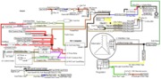
Take a look at Mr Diagram here and you'll see the basic make-up of the Alt circuit.

If you are using a 3G (and it might be similar or same notation for a 2G), the regulator should have IAS terminals.

I is the switch wire (in Tom's diagram, it's light grn/red at the regulator).

S is the stator wire. It goes from the alt harness plug to the stator receptacle.

A is the sense wiring (yellow/white in the diagram). This ideally is run to the battery or solenoid (for remote voltage sensing) but if your new wiring is up to par, I see no reason why you can't connect this to the charge stud on the alternator.

A nice replacement harness that might work well for your wiring connections is like the top product here.

You'll also obviously need a charge cable (4 AWG or numerically lower).


I hope that anyone who sees any errors in my post or line of thinking will correct me.

Good luck.
 
Ok, correct me if I am wrong here.

It seems I need to run a heavy wire from the Alt to battery, connect the yellow/white wire to hot post. The light green/red needs to go to key switched power. and basically the white/black is looped to the regulator from alt.

If anyone else has anything to add feel free.

Thanks for everything Hissin.
 
mattmcdan said:
Ok, correct me if I am wrong here.

The light green/red needs to go to key switched power.
It would be best to run the switch circuit through the stock dash wiring. There's the battery bulb, as well as an in-parallel-resistor (in the event of the bulb failing). Remember, there's 12 volts at one end of that wire and occasional ground at the other end; I would not run a wire straight from 12 volts to the regulator.

Good luck.
 
HISSIN50 said:
It would be best to run the switch circuit through the stock dash wiring. There's the battery bulb, as well as an in-parallel-resistor (in the event of the bulb failing). Remember, there's 12 volts at one end of that wire and occasional ground at the other end; I would not run a wire straight from 12 volts to the regulator.

Good luck.

I don't know if that is an option, for the sake of simplicity. Id rather not go tearing into my dash tracking down wires and resistors. Unless the wires I need are ran to the location of the stock ECM, then I may be able to find them.
 
mattmcdan said:
Hissin, if you read this I forgot to tell you that the car Im doing this with is a 1990 Coupe, there is a volt gauge in dash, but I dont recall a battery light.
After post 8, I figured I'd bow-out for a bit on this thread. But since you asked................

There should be a battery light. If the bulb burned out, the resistor is what keeps the switch wiring from shorting out (circuit failsafe). I dont have a coupe, so I can't comment with any decisiveness however. I'd be shocked to hear that there is no battery light.

Were it me, I'd keep a stock style function. You would not necessarily have to use the stock wiring itself (you could use your own idiot light and resistor - they could even be hidden). It seems to me that you really could just use a resistor (no idiot light) but I like to make things work like factory when I can (so I don't screw myself with something I didn't think of).

All in all, this might involve you running one wire through the firewall and to the alt. Then plumb in the resistor and idiot light. Or just find the OEM switch wire - it should not be that tough.

Just do what seems simplest to you - only you know to what degree the OEM wiring harnesses were removed, etc.

Good luck.
 
EVTM_p012a.jpg
 
Diagram courtesy of Tmoss & Stang&2birds
fuel-alt-links-ign-ac.gif


See the following website for some help from Tmoss (diagram designer) & Stang&2Birds (website host) for help on 88-95 wiring http://www.veryuseful.com/mustang/tech/engine/

http://www.veryuseful.com/mustang/tech/engine/images/IgnitionSwitchWiring.gif

http://www.veryuseful.com/mustang/tech/engine/images/fuel-alt-links-ign-ac.gif

http://www.veryuseful.com/mustang/tech/engine/images/88-91_5.0 _EEC_Wiring_Diagram.gif

The 500 ohm resistor in parallel with the light bulb serves to provide an alternate signal path if the light bulb burns out. The purpose of this circuit is twofold.
1.) It provides an indication that the alternator isn't working when the ignition switch is turned on.
2.) It provides a turn on signal to the alternator regulator when the ignition switch is in the Run position. This tells the regulator to provide power to the alternator field windings.
 

Attachments

  • fuel-alt-links-ign-ac.gif
    fuel-alt-links-ign-ac.gif
    83.1 KB · Views: 139
mattmcdan said:
Hissin, I found my green/red wire today and tracked everything down. I will give it a go and hope everything is ok. Is the above wiring diagram the same for 2G and 3G? I have a 2g alt now, and will upgrade to 3G later when budget allows.
The diagram that Joe posted is for a 2G.

Good luck.