American autowire harness

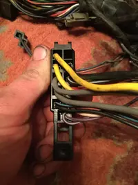
So I went about Buying a new dash harness from american autowire since there was an electrical short in mine and it got burnt up due to 20 years of bad repairs. Directs are pretty straightforward and idiot proof with pictures very very nice quality. My questions are for the ecu hookup and they are very confusing and american autowire was not able to help. They say I have to buy a stand alone system but I believe I can get my stock ECU to work along with my injector harness. My question is were do you thing I should hook these two wires into my ecu according to stock schematics. I would hate to half to buy another 1500 in A stand alone system. Between this and after market gauges I'm 1600 dollars in.
I believe I need key on power ignition and constant battery power. My fuel pump is not an issue because I bought an automotive fuel pump harness for that.
 

Attachments

  • 20190323_224436.webp
    20190323_224436.webp
    393.1 KB · Views: 467
  • 20190325_150536.webp
    20190325_150536.webp
    386.3 KB · Views: 2,858
My question is if you were to hook this kit up or if anyone has used this kit with stock computer for 87 to 89 how did they go about hooking it up for ecu connections. I know the stock dash harness connects to engine harness on passenger side.
 

Attachments

  • 15536395970582870831498319803642.webp
    15536395970582870831498319803642.webp
    154.7 KB · Views: 802
  • 15536396263996394566358432060518.webp
    15536396263996394566358432060518.webp
    129.6 KB · Views: 567
  • 1553639707002341206808453328104.webp
    1553639707002341206808453328104.webp
    144.5 KB · Views: 473
  • 15536397433925681179768997850455.webp
    15536397433925681179768997850455.webp
    133.3 KB · Views: 366
  • 1553639850848629107082937121940.webp
    1553639850848629107082937121940.webp
    163.4 KB · Views: 336
Here's where you can get the stock wiring diagrams for a starting place.

The following are diagrams courtesy of Tmoss & Stang&2birds

Complete computer, actuator & sensor wiring diagram for 88-90 Mass Air Mustangs
88-91_5.0_EEC_Wiring_Diagram.gif


Ignition switch wiring
IgnitionSwitchWiring.gif


See the following website for some help from Tmoss (diagram designer) & Stang&2Birds (website host) for help on 88-95 wiring; http://www.veryuseful.com/mustang/tech/engine/ Everyone should bookmark this site.


TFI module wiring for 94-95 Mustang GT
http://www.veryuseful.com/mustang/tech/engine/images/Mustang-94-95-IgnitionControlModule.gif

Complete computer, actuator & sensor wiring diagram for 94-95 Mustangs
http://www.veryuseful.com/mustang/tech/engine/images/94-95_5.0_EEC_Wiring_Diagram.gif

Complete computer, actuator & sensor wiring diagram for 91-93 Mass Air Mustangs
http://www.veryuseful.com/mustang/tech/engine/images/91-93_5.0_EEC_Wiring_Diagram.gif

Complete computer, actuator & sensor wiring diagram for 88-90 Mass Air Mustangs
http://www.veryuseful.com/mustang/tech/engine/images/88-91_5.0_EEC_Wiring_Diagram.gif

Ignition switch wiring
http://www.veryuseful.com/mustang/tech/engine/images/IgnitionSwitchWiring.gif

O2 sensor wiring harness
http://www.veryuseful.com/mustang/tech/engine/images/mustangO2Harness.gif

Vacuum diagram 89-93 Mustangs
http://www.veryuseful.com/mustang/tech/engine/images/mustangFoxFordVacuumDiagram.jpg

HVAC vacuum diagram
http://www.veryuseful.com/mustang/tech/engine/images/Mustang_AC_heat_vacuum_controls.gif

TFI module differences & pin out
http://www.veryuseful.com/mustang/tech/engine/images/TFI_5.0_comparison.gif

Fuse box layout
http://www.veryuseful.com/mustang/tech/engine/images/MustangFuseBox.gif

Mustang 5.0 Lights and Radio schematic, by TMoss:
http://www.veryuseful.com/mustang/tech/engine/images/mustangFoxLights-Radio_diag.gif

87-92 power window wiring
http://www.veryuseful.com/mustang/tech/engine/images/mustang87-92 PowerWindowWiring.gif

93 power window wiring
http://www.veryuseful.com/mustang/tech/engine/images/mustang93PowerWindows.gif

T5 Cutaway showing T5 internal parts
http://www.veryuseful.com/mustang/tech/engine/images/5_Speed_Cutaway_Illustrated.jpg

Visual comparison of the Ford Fuel Injectors, picture by TMoss:
http://www.veryuseful.com/mustang/tech/engine/images/Ford_Injector_Guide.jpg

Convertible top motor wiring http://www.veryuseful.com/mustang/tech/engine/images/mustang88VertTopMotorCkt.gif

Engine mounted fuel injector harness
http://www.veryuseful.com/mustang/tech/engine/images/mustangEngineHarness.gif

Location of the TPS, IAB, and the 10-pin connectors on a 5.0, picture by TMoss:
http://www.veryuseful.com/mustang/tech/engine/images/TPS_IAB_Pic.jpg

Starter circuit
http://forums.stangnet.com/attachment.php?attachmentid=21328&d=1080916057

Alternator diagram for 94-95 Mustangs.
http://www.veryuseful.com/mustang/tech/engine/images/Mustang-94-95-Alt.gif
 
There’s does not much of the factory stuff they followed it’s all there own. Prob gonna have to wing it. I know the .edu needs a constant battery power and key switch power which is pin 30 and Kapwr is 1. If I can’t figure it out might have to source a used dash harness. And keep this for later
 

Attachments

  • 41D39A2F-8AEC-4C6D-A435-36C02FE7B625.webp
    41D39A2F-8AEC-4C6D-A435-36C02FE7B625.webp
    143.6 KB · Views: 294
  • 12A54956-8F54-437F-B6C4-CCEBBDA668B4.webp
    12A54956-8F54-437F-B6C4-CCEBBDA668B4.webp
    257.2 KB · Views: 259
  • 4158CE4C-5ECD-4D59-A65A-E4E9A1B52A77.webp
    4158CE4C-5ECD-4D59-A65A-E4E9A1B52A77.webp
    182 KB · Views: 244
  • E7DCB077-678F-4232-B304-B57C136B1BB7.webp
    E7DCB077-678F-4232-B304-B57C136B1BB7.webp
    145.1 KB · Views: 256
Edited 28 Mar @ 12:30 EDT
Pins 40 & 60 are computer Ground


DO NOT put power to pin 30!!! you will damage the computer!!!

Pin 30 is the neutral sense switch that tells the computer that the transmission is in neutral..
 
Last edited:
Pins 40 & 60 are computer power from the computer relay.

DO NOT put power to pin 30!!! you will damage the computer!!!

Pin 30 is the neutral sense switch that tells the computer that the transmission is in neutral..
So no power to pin 30 ok cool . So do I want constant battery 12v power to pin 1 because pin 40 and 60 are grounded until they get power once the ignition is turned on get power from computer relay. So I guess I hook up ignition feed to my EEC relay ?
 
So no power to pin 30 ok cool . So do I want constant battery 12v power to pin 1 because pin 40 and 60 are grounded until they get power once the ignition is turned on get power from computer relay. So I guess I hook up ignition feed to my EEC relay ?
That is correct. Check the ignition switch diagram I posted and you will find it there.
 
Well good thing I check harness turns out i have an 91 to 93 harness started cross referencing stuff and my fuel pump relay is in engine harness and my ecm is a a9m which I believe means it's from a 5 speed vert. So have to tap into some different wires.
 

Attachments

  • 20190327_173427.webp
    20190327_173427.webp
    182.4 KB · Views: 258
  • 20190327_173254.webp
    20190327_173254.webp
    73.3 KB · Views: 246
  • 20190327_173220.webp
    20190327_173220.webp
    123.3 KB · Views: 250
Got harness all wrapp

sorry if I’m kinda late. But I just finished the same wiring harness on my 90 foxbody lx and I’m stuck on the same part (which is the last thing I have to do)
so the grey 12v in the run key position and the pink 12v in run and crank key positions both go to the ignition wiring and the 12v orange constant battery power is a loose wire that taps into the ecu pin 1?
i have looked everywhere for help and this is the closest I’ve gotten so anything would help! Thanks!!
Were you able to figure it out? Hopefully this notifies someone